32
CDX-M610
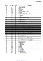
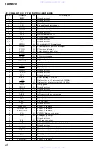
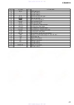
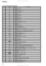
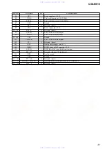
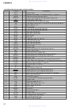
• IC801 MB90574BPMT-G-260-BND (SYSTEM CONTROL)
Pin No.
Pin Name
I/O
Pin Description
1
(NCO)
O
Not used. (Open)
2
(AMSIN)
I
Inter-music detection input (“H”: inter-music) (Fixed at “L” in this set.)
3
(AMSON)
O
AMS sens select output (Not used in this set.)
4
SP LATCH
O
Spectrum analyzer display data latch signal output to display micon.
5
ATT
O
System attenuate control output
6
SYSRST
O
Resetting for slave micon of SONY BUS system.
7
(N/R)
O
Forward/Reverse select output (“L”: forward, “H”: reverse) (Not used in this set.)
8
VCC
—
Power supply pin (+5 V)
9
(NCO)
O
Not used. (Open)
10
E2PSIO
I/O
Tuner EEPROM communication input/output
11
E2PCKO
I/O
Tuner EEPROM communication input/output
12
FLS SI
I
Flash micon write data input
13
FLS SO
O
Flash micon write data output
14
BUS-ON
O
BUS ON output
15
BEEP
O
Beep output
16
TELATT
I
Telephone mute input (“H”: mute ON)
17
UNISI
I
SONY BUS serial data input
18
UNISO
O
SONY BUS serial data output
19
UNICKO
O
SONY BUS serial clock output
20
IFWIDTH
O
Not used. (Open)
21, 22
(NCO)
O
Not used. (Open)
23
(MTLOUT)
O
Tape metal signal output (“H”: metal) (Not used in this set.)
24
SIRCS
I
Wireless remote data input
25
DSPSI
I
Digital signal processor serial data input
26
DSPSO
O
Digital signal processor serial data output (Not used in this set.)
27
DSPCKO
O
Digital signal processor clock output (Not used in this set.)
28
(DSPPLL)
O
Not used. (Open)
29
DSPMST
O
Digital signal processor master slave control output (Not used in this set.)
30
SW SHIFT
O
Tuner SW (Short Wave) signal output (“H”: SW signal receipt) (Not used in this set.)
31
VOLATT
O
Electronic volume mute output (“L”: mute ON)
32
TU ATT
O
Tuner mute output (“H”: mute ON)
33
VSS
—
Ground
34
C
—
Power stabilization capacitor pin
O
Digital signal processor latch output (Not used in this set.)
O
Digital signal processor reset output (Not used in this set.)
O
DC/DC converter oscillation frequency shift output (“H”: shift output)
—
VREF input of D/A converter.
—
Ground of D/A converter.
O
Front panel OPEN/CLOSE motor voltage control output
O
Not used. (Open)
—
Analog power supply pin (+5 V)
—
VREF+ input of A/D converter. (+5 V)
—
VREF– input of A/D converter.
45
AVSS
—
Analog ground
46, 47
KEYIN0, 1
I
Key input 0, 1
48
RCIN0
I
Rotary commander input 0
49
(NCO)
—
Not used. (Open)
50
QUALITY
I
Noise detection input (Not used in this set.)
51
FM AGC
I
FM suppression level detection input
52
MPTH
I
Tuner multi path detection input
53
VSM
I
S-meter voltage detection input
www. xiaoyu163. com
QQ 376315150
9
9
2
8
9
4
2
9
8
TEL 13942296513
9
9
2
8
9
4
2
9
8
0
5
1
5
1
3
6
7
3
Q
Q
TEL 13942296513 QQ 376315150 892498299
TEL 13942296513 QQ 376315150 892498299


