MEX-GS610BE/GS610BT/N6050BT
MEX-GS610BE/GS610BT/N6050BT
25
25
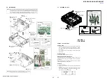
3-6. MAIN BOARD
MAIN board
C501
C848
:LUHVHWWLQJ
filament tape
REGULATOR
board
[blue]
C501
[red]
[black]
C848
front side
filament
tape
6
Remove the
MAIN board block
in the direction
of the arrow.
0
MAIN board
5
claw
5
claw
1
lead wire with connector
(CN1002)
:LUHVHWWLQJ
OK
NG
connector
connector
lead wire with connector
lead wire with connector
3
two ground point screws
(PTT2.6
u
6)
4
screw
(PTT2.6
u
8)
4
screw
(PTT2.6
u
8)
9
filament
tape
lead wire from antenna BT
antenna BT
front side
MAIN board
connector
(CN1002)
3
ground point screw
(PTT2.6
u
6)
2
filament
tape
7
Remove the
solder.
[red]
7
Remove the
solder.
[black]
7
Remove the
solder.
[blue]
8
REGULATOR board block
SECTION 4
TEST MODE
SETTING THE TEST MODE
Setting method:
1. In the state of source off (the clock is displayed), enter the test
mode by pressing the buttons in order of the [ 4]
t
[MIC
5]
t
[
V
ALBUM 1] (press only the [
V
ALBUM 1] button for
two seconds).
2. It is set to the test mode, and all segments of the liquid crystal
display light.
Releasing method:
Press the [
OFF SRC] button for 1 second.
MICROPHONE AUDIO LOOPBACK
To con
fi
rm the state of the external microphone used when a
handsfree function is used, the microphone audio is output from
the speaker.
The breakdown judgment of the microphone can be done without
connecting H/F with the cellular phone.
Procedure:
1. Enter the test mode.
2. Press the [
OFF SRC] button to select the Bluetooth Phone
function.
3. On/off of the microphone audio loopback function changes
whenever the [ALBUM
v
2] button is pressed (“ ” is dis-
played on the liquid crystal display).
LOOPBACK
ON
Lit
OFF
None
3-7. ANTENNA BT (BT1)
:LUHVHWWLQJ
connector
connector
lead wire with connector
lead wire with connector
4
screw (T)
5
antenna BT
(BT1)
3
lead wire with connector
(CN1002)
OK
NG
2
connector
(CN1300)
1
Remove the cable
from lead pin.
lead wire from antenna BT
antenna BT
lead pin
front side
MAIN
board
connector
(CN1002)
connector
(CN1300)
Note 1:
When the complete MAIN board is replaced, it is necessary to replace knob (VOL) (SV)
assy simultaneously. Also, the destination setting, Bluetooth operation check and Bluetooth
information writing is necessary. Refer to “DESTINATION SETTING METHOD” on page
4, “BLUETOOTH FUNCTION CHECKING METHOD USING A CELLULAR PHONE”
on page 7 and “BLUETOOTH INFORMATION WRITING METHOD” on page 8.
Note 2:
REGULATOR board has been deleted in the midway of production.
For details, please refer to service manual supplement-1.
Содержание CDX-G3000UE
Страница 14: ...MEX GS610BE GS610BT N6050BT 14 MEMO ...
Страница 58: ...58 MEX GS610BE GS610BT N6050BT MEMO ...
Страница 75: ...MEMO MEX GS610BE GS610BT N6050BT 17 ...


