– 25 –
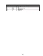
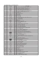
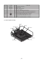
Pin No.
Pin Name
I/O
Pin Description
56
AMP ON
O
Power amplifier power control output
57
XMODE
O
Reset output to CD-TEXT decoder IC. (Not used in this set.)
58
VOL SO
O
Main volume serial data output
59
VOL CKO
O
Main volume serial clock output
60
AU MUTE
O
System attenuate control output
61
AF MUTE
O
Attenuate output at AF operation of RDS. (Not used in this set.)
62
TU MUTE
O
Tuner attenuate output (Not used in this set.)
63
VSS
—
GND
64
ACC IN
I
Accessory power detection input
65
AF SEEK
O
AF operation control output of RDS. (Not used in this set.)
66
M SIO
I/O
EEPROM serial data input/output (Not used in this set.)
67
DAVN
I
RDS IC data taking in detection input
68
M CK
O
EEPROM serial clock output (Not used in this set.)
69
M CE
O
EEPROM chip enable output (Not used in this set.)
70
RDS SI
O
RDS serial data input (Not used in this set.)
71
RDS CKI
O
RDS serial clock input (Not used in this set.)
72
RC IN1
I
Rotary commander shift key input
73
X1A
—
Low speed oscillation input 1
74
X0A
—
Low speed oscillation input 0
75
SCOR
I
SCOR signal detection input (Connected to GND.)
76
BU-IN
I
Back-up power detection input
77
DQSY
I
CD-TEXT data set complete signal detection input (Connected to GND.)
78
CD SENS
I
CD SENS signal detection input (Connected to GND.)
79
KEY ACK
I
Key input detection input at power OFF.
80
TEL MUTE
I
Telephone attenuate detection input
81
ST IN
I
Tuner stereo signal detection input
82
SEEKOUT
O
MW/LW SEEK output
83
SD IN
I
Signal detector input
84
MONO
I
Not used in this set.
85
PLL CE
O
PLL chip enable output
86
H
—
Hardware standby input
87
VSS
—
GND
88, 89
VCC
—
Power supply pin (+5 V)
90
RESET
—
Reset input
91
VSS
—
GND
92
X0
—
High speed oscillation input 0
93
X1
—
High speed oscillation input 1
94
VCC
—
Power supply pin (+5 V)
95
PW SEL
I
Power select initial setting input
96
POL MONO
I
Not used in this set.
97
AREA1
I
Destination select input 1 (Fixed at “L” in this set.)
98
AREA2
I
Destination select input 2 (Fixed at “H” in this set.)
99
AREA3
I
Destination select input 3 (Fixed at “L” in this set.)
100
BAND (9K/10K)
I
Band plan setting general area
101
POL ST
I
Not used in this set.
102
NIL
I
Connected to GND.
103
NIL
I
Connected to GND.
104
LCD CE
O
LCD chip enable output
105
NIL
I
Fixed at “H” in this set.
106
RE0
I
Rotary encoder input 0
107
RE1
I
Rotary encoder input 1
108
LAMP ON
O
Illumination power control output
Содержание CDX-4480ESP - Am/fm Compact Disc Changer
Страница 4: ... 4 SECTION 1 GENERAL This section extracted from instruction manual ...
Страница 5: ... 5 ...
Страница 6: ... 6 ...
Страница 7: ... 7 ...
Страница 8: ... 8 ...
Страница 9: ... 9 ...
Страница 10: ... 10 ...
Страница 29: ......
Страница 30: ......
Страница 31: ......
Страница 32: ......
Страница 33: ......

