background image

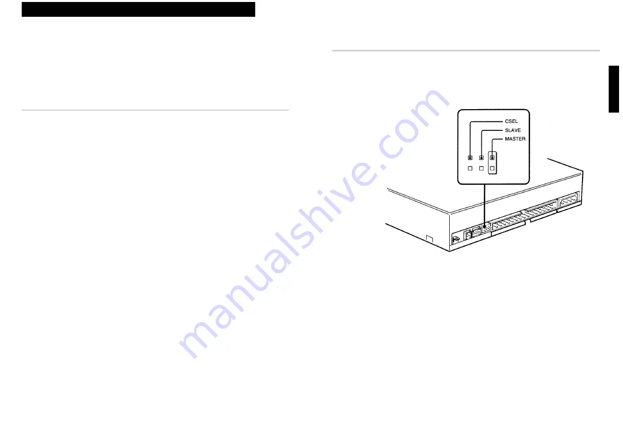
Setting the Jumpers

Set the jumpers on the rear of the drive in accordance with the
configuration of your computer system.
The jumpers are preset at the “MASTER” position as illustrated at the
factory.

Notes for configuration jumpers:

Designation of the Drive Number is generally set by inserting a jumper 
pin on either the MASTER or the SLAVE pin.

When the CDU77E is daisy-chained with a Hard Disk Drive on an IDE 
Card, set the Hard Disk Drive as MASTER and the CDU77E as 
SLAVE.

If the CDU77E is the only device connected to the IDE Card, set the 
CDU77E as MASTER.

However, it should be noted that some personal computers may use CSEL
in lieu of the foresaid MASTER/SLAVE selection. In this case, remove the
existing jumpers from MASTER and SLAVE, and set a jumper on CSEL.
When the CSEL signal of the interface connector is set low, the drive is
designated as Drive 0. When the CSEL is set high, the drive is designated
as Drive 1.
Consult your PC manufacturer, IDE Card manufacturer or dealer for
further details.

Installing the Drive in Your Computer

11

English

Installing the Drive in Your Computer

This section provides an example of instruction for installing the CD-ROM
drive unit into your personal computer.
To connect the CDU77E directly to the PC’s IDE port, consult your PC
manufacturer for instruction.

Preparation

You need the following parts and tools (these are not supplied with the
drive):

A flat-blade screwdriver

Four screws 3 mm in diameter and 6 mm in length.

Two mounting rails if your computer has mounting tracks.

Unplug the computer and disconnect the cables attached to the back to
give yourself more room to work. Do not turn on the power of the
computer before completing the entire installation process.

10

Installing the Drive in Your Computer

Содержание CDU77E

Страница 1: ...CDU77E CD ROM Drive Unit User s Guide 1995 by Sony Corporation CDU77E CD ROM Drive Unit User s Guide ...

Страница 2: ... PC PC XT and PC AT are registered trademarks of International Business Machines Corporation HP Vectra is a registered trademark of the Hewlett Packard Company Molex is a registered trademark of Molex Inc AMP is a registered trademark of AMP Inc This CD ROM Drive Unit is classified as a CLASS 1 LASER PRODUCT The CLASS 1 LASER PRODUCT label is located on the top of the drive Bei diesem CD ROM Laufw...

Страница 3: ...e error correction Fast access time ensuring reliable high speed data access Audio Outputs 16 bit digital audio data over the ATA PI interface Equipped with audio line output and headphones jack for audio CD playback Note The CDU77E is not equipped with an ADPCM audio circuitry required to support CD ROM XA and CD I compatible audio modes In addition the unit does not support the CD I graphic deco...

Страница 4: ...ergency eject hole Used to open the disc drawer manually when neither the eject button 6 nor a software command works Insert a pointed object such as a paper clip into this hole and push 6 Eject button Opens and closes the disc drawer Software Requirement To access data on CD ROM discs the appropriate device driver and MSCDEX or its equivalent must be installed in your computer The application sof...

Страница 5: ... stop using the drive and leave the power on at least one hour before operating it or turning it off Operating the drive immediately after a sudden increase in temperature may result in a malfunction Transportation Close the disc drawer before moving the drive Keep the original packing materials When you need to ship the drive to another location repacking it in its original container will help yo...

Страница 6: ...EL signal of the interface connector is set low the drive is designated as Drive 0 When the CSEL is set high the drive is designated as Drive 1 Consult your PC manufacturer IDE Card manufacturer or dealer for further details Installing the Drive in Your Computer 11 English Installing the Drive in Your Computer This section provides an example of instruction for installing the CD ROM drive unit int...

Страница 7: ...3 English Opening the Computer 1 If your computer has its rear side covered by a plastic panel attached with plastic hook pad pull it off 2 Remove the cover mounting screws 3 Remove the cover of the computer 12 Installing the Drive in Your Computer Computer Remove a plastic panel Cover mounting screw Remove the screws Remove the computer cover Rear plastic panel Floppy disk drive Lower drive bay b...

Страница 8: ...tor and push it firmly in place Caution Improper connection may damage the drive and void the warranty Installing the Drive in Your Computer 15 English Mounting the Drive If mounting rails are necessary attach them to the drive in the same way as your floppy disk drive and slide the drive into the lower drive bay If mounting rails are not required in your system screw the drive in place 14 Install...

Страница 9: ...ation section if you answered no to either of the questions above Installing the Drive in Your Computer 17 English Reinstall the floppy disk drive Tuck the cables Power supply F GND tab Connect the F GND tab to one of the host computer s ground cables unless the drive s frame is in direct contact with the computer s chassis a situation not likely under normal circumstances The frame ground cable r...

Страница 10: ... to loading the installation diskette make sure that the MSCDEX is in the DOS directory of your hard disk drive C DOS Although MSCDEX is included in the most up to date MS DOS ver 6 2 you may need to obtain the software from your PC dealer if you do not have it The installer will automatically load MSCDEX via the AUTOEXEC BAT file and installs the Device Driver via the CONFIG SYS file if MSCDEX is...

Страница 11: ...tton to close the drawer The drive may begin reading the Table of Contents TOC data when it accepts the disc The busy indicator lights up in amber while the drive is reading the TOC For subsequent drive operations follow the instructions provided with the application software you are using Note The busy indicator stays lit in amber if the disc is not properly placed on the loading tray a malfuncti...

Страница 12: ...he Disc Locks The disc tray has four disc locks that prevent the disc from falling when the drive is set up in vertical position Note When the drive is used in horizontal position you do not need to lock the disc Locking and unlocking All of the four locks are set in the unlocked position facing outward when the drive is shipped from the factory To set the lock in the locked position turn it with ...

Страница 13: ...Host interface ATA PI interface Disc Acceptable discs CD Digital Audio discs CD ROM mode 1 data discs CD ROM mode 2 form 1 form 2 data discs CD ROM XA discs readable Audio combined CD ROM discs CD I discs readable CD I Ready discs readable CD Bridge discs Photo CD discs single and multi session Disc diameter 12 cm or 8 cm Drive performance Data transfer rate Sustained rate 150 kbytes s normal 300 ...

Страница 14: ...xceed 6 0 mm from the surface of the side panels or the bottom plate 26 Specifications 5 1 2 17 8 31 8 79 25 47 5 139 7 10 1 32 1 32 21 9 7 8 13 32 0 5 0 4 1 11 16 41 4 5 111 16 42 3 203 8 146 5 3 4 7 32 148 5 7 8 4 M3 mounting screws 4 on each side 4 M3 mounting screws ...

Отзывы: