background image

98

Displaying the Monitor Status Page

  Cha

p

te

r 4  

 Op

er

at

ions

3

Press the ENTER (Ent) button.

The data is saved in the “Memory Stick”.

• Use the controller with software version 1.6 or higher for 

data saving, copying and deleting using the “Memory 
Stick”.

• Data saving, copying and deleting using the “Memory 

Stick” is not available on BKM-15R or BVM-A14F5.

• Data copying from the BVM-A, PVM-L or BVM-L 

series monitor is not available.

Displaying the Monitor 
Status Page

When Status has been assigned to a function button of the 
controller, various information, such as the setting status, 
display mode, and input signal information of the currently 
displayed video signal, are displayed on the monitor status 
pages.

For how to assign a function to a function button, see 
“Assigning a Function to a Function Button” (page 100).

• To assign Status to a function button of the controller, 

use the controller with software version 1.6 or higher.

• Pixel Zoom is not set to on when the monitor status page 

is displayed.

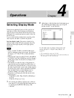
1

Press the Status button on the controller to set it to On.

Page 1/4 of STATUS display is displayed.

2

Select the STATUS page you wish to view using the 
UP/DOWN button on the controller.

You can select the page from among 1/4, 2/4, 3/4 and 
4/4.

For the contents of each page, see below.

To cancel the display of the STATUS page

Press the Status button on the controller again.

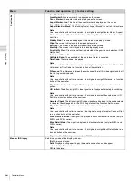
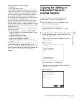
Page 1/4

Information on the setting status of the input signal and the 
display mode is displayed.

CH: 

Displays the currently selected channel number and 

channel name.

Detected Signal: 

Displays the signal system whose format 

is detected.

Format: 

Displays Format set in the Channel 

Configuration menu.

Notes

Notes

STATUS (Input / Display Mode) 

1/4

 CH: 

01 "PROG1"

 Detected Signal: 

1080/60I 

    For mat: 

4:4:4 RGB 10bit 

   Input Por t: 

Option1/Input1

 RGB Range: 

Limited

 1080I/PsF: 

1080I

 Scan Mode: 

Native Aspect Correct 

   Aspect Mode: 

16:9

 Interlace Display: 

ON

v

V

Содержание BVM-E250

Страница 1: ...PROFESSIONAL VIDEO MONITOR BVM E250 OPERATION MANUAL English 1st Edition Revised 3 ...

Страница 2: ...d or plug is damaged liquid has been spilled or objects have fallen into the apparatus the apparatus has been exposed to rain or moisture does not operate normally or has been dropped WARNING To reduce the risk of fire or electric shock do not expose this apparatus to rain or moisture To avoid electrical shock do not open the cabinet Refer servicing to qualified personnel only THIS APPARATUS MUST ...

Страница 3: ...ase consult a qualified service personnel For the customers in Canada This Class A digital apparatus complies with Canadian ICES 003 For the customers in Europe This product with the CE marking complies with the EMC Directive issued by the Commission of the European Community Compliance with this directive implies conformity to the following European standards EN55103 1 Electromagnetic Interferenc...

Страница 4: ... alimentation fiche femelle fiche mâle ci dessus consultez un technicien du service après vente qualifié Pour les clients en Europe Australie et Nouvelle Zélande AVERTISSEMENT Il s agit d un produit de Classe A Dans un environnement domestique cet appareil peut provoquer des interférences radio dans ce cas l utilisateur peut être amené à prendre des mesures appropriées WARNUNG Um die Gefahr von Br...

Страница 5: ...nen Stecker mit den geeigneten Anschlusswerten Volt Ampere Wenn Sie Fragen zur Verwendung von Netzkabel Geräteanschluss Stecker haben wenden Sie sich bitte an qualifiziertes Kundendienstpersonal Für Kunden in Europa Australien und Neuseeland WARNUNG Dies ist eine Einrichtung welche die Funk Entstörung nach Klasse A besitzt Diese Einrichtung kann im Wohnbereich Funkstörungen verursachen in diesem F...

Страница 6: ...the Channel 29 Setting the Display Mode of the Picture 30 Adjusting 30 Chroma Phase Adjustment 30 Color Temperature White Balance Adjustment 31 Brightness Contrast Adjustment 32 Chapter 3 Menu Basic Menu Operations 33 Menu Operation Buttons 33 Displaying the Menu 34 Setting or Adjusting in the Menu Operation 34 Entering the Channel Number 36 Aborting Menu Operation 36 Menu Structure 37 Adjustment ...

Страница 7: ...Button 100 Assigning a Function to a Function Button 100 Displaying the Assigned Functions Collectively 100 Upgrading the Monitor and Controller 101 Saving the Upgrade Data in a Memory Stick PRO 101 Upgrading the Monitor 102 Upgrading the Controller 103 Appendixes Specifications 104 Input Signals and Adjustable Setting Items 107 Available Signal Systems 109 Available Signal Formats 111 Aperture Mo...

Страница 8: ...nd the unit for ventilation Leave more than 40 cm of space in the rear of the unit to secure the operation area When the unit is installed on the desk or the like leave at least 1U 4 4 cm or more of space above and below the unit Leaving 40 cm or more of space above the unit is recommended for service operation Handling the Screen The panel fitted to this unit is manufactured with high precision t...

Страница 9: ...een is vulnerable to damage Do not scratch or knock against it using a hard object Be sure to disconnect the AC power cord from the AC outlet before performing maintenance The surface of the screen is specially coated Do not attach adhesive objects such as stickers on it The surface of the screen is specially coated Do not touch the screen directly Wipe the screen surface gently with the supplied ...

Страница 10: ...ion menu The settings for the DisplayPort signal are available 50 55 HDMI DisplayPort Auto in the Matrix menu of the Channel Configuration menu in the RGB Range menu of the Channel Configuration menu Matrix switching Matrix and quantization range setting RGB Range for the HDMI or DisplayPort signal are available 52 55 HDMI DP YCbCr HDMI DP RGB in Input Detection of the Gamut Error Display menu of ...

Страница 11: ...les stored in a Memory Stick can be loaded into or deleted from the monitor Information related to ASC CDL are displayed collectively on the STATUS page 53 57 99 User LUT in the Color Profile menu of the Channel Configuration menu in the Auxiliary Setting menu 3 on the STATUS page The User LUT data for the Color Profile setting can be selected The User LUT data files stored in a Memory Stick can b...

Страница 12: ...e a unique microcavity structure makes RGB primary colors purer and deeper by utilizing light resonance effects that magnify optimum light wave lengths and diminish undesired light wave lengths The panel s 10 bit driver enables smooth gradation of color shading 2 Super Top Emission is a trademark that represents the OLED technology of Sony Corporation 12 bit precision display engine for profession...

Страница 13: ...io for the H direction and the picture is also optimized and displayed by modifying the aperture coefficient value filter coefficient value etc in Aspect Correction mode For the operation see Selecting the Native Scan Scan Mode on page 89 Gamut error function The signal outside the specified range gamut error caused by the conversion of the format or during CG CM production is displayed in a zebra...

Страница 14: ...ll image is displayed continuously for 10 minutes or more the screen saver starts automatically to reduce the brightness of the screen to prevent burn in Variable picture adjustment functions Auto chroma phase and matrix adjustment functions are equipped ASC CDL and User LUT functions The ASC CDL American Society of Cinematographers Color Decision List function and the User LUT User Look up Table ...

Страница 15: ...are equipped BKM 227W NTSC PAL Input Adaptor Includes a decoder for NTSC PAL PAL M SECAM signals Input output connectors for each one composite signal channel and Y C signal channel are equipped BKM 229X Analog Component Input Adaptor Includes a decoder for analog component signals and analog RGB signals Input connector for one channel is equipped BKM 243HS HD D1 SDI Input Adaptor Includes a decod...

Страница 16: ...nectors and input adaptors a Signal can be reproduced a 2 Two adaptors are used For details see Available Signal Formats on page 111 Input signal Standard input Input adaptor BKM 220D BKM 227W BKM 229X BKM 243HS 244CC BKM 250TG Serial digital input Single link SD SDI Component 525 625 a a a a Single link HD SDI a a a Dual link HD SDI a 2 a Single link 3G SDI a a Analog input Composite NTSC a Compo...

Страница 17: ...n in the Power menu page 73 of the System Configuration menu and the MAIN POWER switch on the left side panel is turned on The OPERATE lamp will flash for initialization after the switch is turned on then will light The monitor is changed from operation mode to standby mode by external control Lights in green when the monitor is put into operation mode from standby mode by pressing the MONITOR I 1...

Страница 18: ... Error warning display by the lamp The OVER RANGE lamp OPERATE lamp and or ECO lamp on the front panel may show an error or warning while the monitor is being operated If the error or warning is shown please contact your Sony representative Error display Warning display Status except for error display ECO lamp OVER RANGE lamp OPERATE lamp Symptoms Lights in yellow Lights in amber Flashes in red Th...

Страница 19: ...device wiring that might have excessive voltage to this port Follow the instructions for this port When you connect the LAN cable of the unit to peripheral device use a shielded type cable to prevent malfunction due to radiation noise The connection speed may be affected by the network system ATTENTION Par mesure de sécurité ne raccordez pas le connecteur pour le câblage de périphériques pouvant a...

Страница 20: ...gy that incorporates coding technology for digital video signals The HDMI audio signal is not available for this monitor Use HDMI compliant cable optional Category 2 High Speed HDMI Cable with HDMI logo g DisplayPort input connector Inputs the DisplayPort signal DisplayPort is an interface developed by VESA that supports transfer of both video and audio digital signals on a single cable It also su...

Страница 21: ...ctromagnetic interference standard if designated input adaptors are not installed BKM 227W with serial number 2100001 or higher This equipment may not work correctly or you may not be satisfied with their performance if designated input adaptors are not installed BKM 229X with serial number 2200001 or higher This equipment may not work correctly or you may not be satisfied with their performance i...

Страница 22: ...d install the input adaptors in OPTION 1 and 2 option ports or OPTION 3 and 4 option ports The BKM 243HS or BKM 244CC cannot be used with the BKM 250TG for Dual link operation To connect the cable When the BKM 243HS or BKM 244CC adaptors are used install the Link A signal to OPTION 1 or 3 and the Link B signal to OPTION 2 or 4 Connect the cable to the same input number both INPUT 1 or both INPUT 2...

Страница 23: ...001 or higher and input the left 3D signal to INPUT 1 and the right signal to INPUT 2 Attaching the Bracket You can prevent falling of the monitor by using the supplied bracket 1 Remove three screws from the bracket 2 Attach the bracket on the rear panel of the monitor with the three removed screws 3 Attach a piece of string etc to the bracket and secure it to the floor or wall INPUT 2 INPUT 1 Bra...

Страница 24: ...0 connector of the controller by using the SMF 700 or the cable supplied with the BKM 37H 38H or a 10BASE T 100BASE TX straight LAN cable shielded type optional When an optional LAN cable is connected use a shielded type cable to prevent a malfunction due to noises 4 Connect the DC 5V OUT connector of the monitor and the DC 5V 12V IN connector of the controller by using the SMF 700 or the cable su...

Страница 25: ...ype cable to prevent a malfunction due to noises We recommend to use an optional switching hub with auto selection function AUTO MDI MDI X of a straight cross cable 3 Connect the output cable on the AC adaptor supplied with controller to the DC 5V 12V IN connector of the controller When the multiple units are connected set for the LAN before setting the NETWORK switch to LAN page 28 4 Set the NETW...

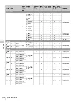
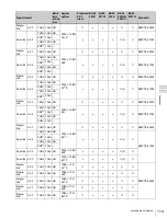
Страница 26: ...nel to turn on the power When you turn on the monitor for the first time after purchasing it the Select Area screen is displayed Select the area where you intend to use this monitor For selecting the area see page 27 The warm up time is more than 30 minutes approximately When the monitor is in standby mode As the OPERATE lamp lights in red in standby mode press the MONITOR I 1 switch of the contro...

Страница 27: ...ER Ent button Color Temp Setup Level Component Level Color Profile 1North America D65 7 5 Betacam ITU R BT 709 2Latin America Argentina D65 0 SMPTE EBU N10 ITU R BT 709 PAL PAL N Area Paraguay D65 0 SMPTE EBU N10 ITU R BT 709 Uruguay D65 0 SMPTE EBU N10 ITU R BT 709 NTSC PAL M Area Other Area D65 7 5 Betacam ITU R BT 709 3Africa Australasia Europe Middle East D65 0 SMPTE EBU N10 ITU R BT 709 4Asia...

Страница 28: ...ach LAN 10 100 connector You can also control a specific monitor or monitor group Set an IP address to the monitors and the controller and a monitor ID number and group ID number to each monitor 1 Set the NETWORK switches of each monitor and the controller to PEER TO PEER 2 Set the different IP address to each monitor and the controller Monitor Set the IP address in the Network Setting menu page 7...

Страница 29: ...the monitor ID number for the single connection mode or group ID number for the group connection mode by pressing the UP DOWN or numeric button Up to 99 is entered as the monitor ID or group ID number 3 Press the ENTER or Ent button to confirm the setting The monitor ID number group ID number or ALL is displayed in the display window When the monitor with no assigned monitor ID number or group ID ...

Страница 30: ...equence 1 Chroma phase adjustment You can save the adjustment value in Preset1 to Preset5 and Preset D Cine The data of Preset1 to Preset5 or Preset D Cine is set to the channel in the Picture Preset menu page 51 of the Channel Configuration menu Adjust the picture automatically with the auto chroma phase matrix function for every signal format and signal system to display the composite signal or ...

Страница 31: ... the levels with the CHROMA and PHASE knob For the component signal Adjust the levels with the CHROMA knob 5 Press the ENTER or Ent button The adjusted data is confirmed 6 Set the BLUE ONLY button to off You can access manual adjustment without opening the Adjustment menu To access it press the MANUAL button located below the CHROMA or PHASE knob of the controller If manual adjustment is accessed ...

Страница 32: ...t the 2 and 0 ranges are seen as equal and the 2 and 0 ranges are more distinctive SD signal Adjust so that the 0 and 2 ranges are seen as equal and the 2 and 4 ranges are more distinctive 4 Adjust so that the luminance of the 100 white signal of the color bar is set to the desired value with the CONTRAST knob We recommend adjusting the luminance to 100 cd m2 when Preset1 to Preset5 is selected in...

Страница 33: ...reases the setting or adjustment value 2 MENU button Displays the menu Goes back to the menu of the upper level On the main menu goes back to the normal picture 3 ENTER button Changes an item or displays the information on the functions assigned to function buttons In setting mode confirms the adjustment or setting value 4 PHASE knob By turning this knob clockwise the cursor moves downward In sett...

Страница 34: ...The method for selecting the value is different due to the menu item Selecting in setting mode Selecting from the setting list Notes MENU Adjustment B Channel Configuration B Auxiliary Setting B Function Setting B System ConfigurationB File Management B System Status B Controller B Key Protect xxx MENU Adjustment B Channel Configuration B Auxiliary Setting B Function Setting B System Configuration...

Страница 35: ...c buttons and press the ENTER or Ent button only the item whose the value of setting range is over 0 Select the value using the UP or DOWN button Select the value using the PHASE knob 3 Press the ENTER or Ent button The setting is confirmed and the cursor returns to the item Entering characters 1 Using the UP or DOWN button or PHASE knob select New Name or the existing name The means that one or m...

Страница 36: ...mber press the button of the channel number When selecting a two digit number first press the 0 button then press a two digit channel number Channel numbers 91 to 97 assignment The signal systems to which the internal signal is displayed are assigned to channel numbers 91 to 97 The internal signal of the last signal system is displayed 091 PLUGE signal 092 20 gray signal 093 100 white signal 094 F...

Страница 37: ...olor Bar Restore Factory Data Status Input Port Format Matrix Manual Adjust Copy From Preset Value Other Monitor Monitor ID Memory Stick Color Temp Adj Manual Manual Adjust Original Value Signal Contrast Bright Hold Copy From Preset Value Other Monitor Monitor ID Memory Stick Restore Factory Data Position Adj H Shift V Shift Main menu Level 1 Level 2 Level 3 Level 4 ...

Страница 38: ...ace Gamma ASC CDL File User LUT File Color Space Gamma Marker Preset H Shift Offset Channel Name NTSC Setup Level Component Level Betacam Setup Level RGB Range HD DC 2048 1080 HDMI DisplayPort HDMI DisplayPort Auto 1080I PsF 24PsF 25PsF 50I 30PsF 60I Film Cadence Copy From Other CH Other Monitor Monitor ID Memory Stick Main menu Level 1 Level 2 Level 3 Level 4 Auxiliary Setting ASC CDL Load ASC CD...

Страница 39: ...Marker 2 Area Marker 2 Aspect Mode Aspect Area Size Width Height Mode Thickness Color Bright Center Marker Center Marker Mode Color Bright H Position V Position Copy From Preset Value Other Monitor Monitor ID Memory Stick P P Setting Side by Side Line Display Line Color Line Bright Wipe Line Display Line Color Line Bright Position Butterfly Line Display Line Color Line Bright Position Blending Ble...

Страница 40: ... Limit G B R Post Process Detection Detection Pixel Threshold Signal Level Upper Limit Lower Limit Zebra Pattern Line Modulation 3D Setting Horopter Check Left Right Capture Load Rename Delete Internal Signal Function Switch Scan Mode Native Scan 16 9 H Delay V Delay External Sync Comb Aperture Mono Blue Only R Off G Off B Off Chroma Up Interlace Marker Aspect Marker Area Marker 1 Area Marker 2 Ce...

Страница 41: ... CH No Position CH Name Position Scan Mode Position Closed Caption Closed Caption Type Service 708 Service 608 OSD Level Audio Level Meter Audio CH Position Transparency Peak Hold Time Code VITC LTC Position Level Over Range Password Change Password Apply Password Adjustment Channel Configuration Auxiliary Setting Function Setting System Configuration Individual Item Network Parallel Remote File M...

Страница 42: ...3 Level 4 System Status CH Status Port Status Option1 Option4 Model Name Serial No SDI Payload ID Status Payload ID Video Standard Sampling Structure Bit Depth Picture Rate Scanning Method Link Number Current Status Format I PsF P HDMI DP Status Pixel Encoding Color Depth Matrix RGB Range Model Name Serial No Software Version Operation Time Panel On Time Network Switch Controller Status Model Name...

Страница 43: ...ntact Name Location Trap Mode Trap Address Setting Trap Address Status Reset Mode Address Authentication Community Protocol Setting SDCP SDAP Community SDCP Port No SDAP Port No SDAP Broadcast SDAP Broadcast Period Reset Protocol Setting Function Key F1 F16 Monitor ID Display Controller Upgrade Software Upgrade Kernel Upgrade Key Protect Main menu Level 1 Level 2 Level 3 Level 4 ...

Страница 44: ...nu of the Channel Configuration menu page 49 Auto Sets the automatic adjustment of chroma phase matrix and signal level When the item is selected the selected preset data is displayed You can select this item when the composite or Y C signal from the BKM 227W or the analog component or analog RGB signal from the BKM 229X is displayed Note This menu is not selectable when the internal signal or cap...

Страница 45: ...to 2000 1000 Bright 500 to 500 000 Contrast 0000 to 2500 1000 for Preset1 to Preset5 0480 for Preset D Cine To display no characters on the screen while adjusting manually Set the CHAR OFF button to on The characters disappear To display characters set the CHAR OFF button to off To reset the setting to the default Press the corresponding MANUAL button The adjusted value is reset to the default To ...

Страница 46: ...re Preset menu page 51 of the Channel Configuration menu Manual Adjust Adjusts the color temperature using the PHASE CHROMA PHASE and or CONTRAST knobs When the item is selected the color temperature adjustment display appears and the Red Green and or Blue color temperature data to be adjusted are displayed to allow gain or bias adjustment Select gain or bias adjustment using the UP DOWN buttons T...

Страница 47: ... in this monitor Except for the XYZ format signal When the item is selected you can select from D93 D65 D61 D55 D Cine User1 User2 User3 User4 or User5 D93 Copies the color temperature of D93 D65 Copies the color temperature of D65 D61 Copies the color temperature of D61 D55 Copies the color temperature of D56 D Cine Copies the color temperature of D Cine User1 to 5 Copies the color temperature of...

Страница 48: ...tory Data Resets the color temperature to the default setting You cannot select this when the setting is the default value The following message appears to confirm the data reset operation Restore factory data OK To reset the data press the ENTER Ent button Cancel To cancel press the MENU button Position Adj Adjusts the position of the picture when the analog signal is input When the item is selec...

Страница 49: ...vel xxxxx Betacam Setup Level xxx RGB Range B 1080I PsF B Film Cadence xxx v V iChannel Configuration 3 3 CH01 Copy From B v V Note Menu Function and operation factory setting Format Sets the input signal type Note The default setting is 3G HD SD SDI Auto 3G HD SD SDI Sets the serial digital signal format Single link 3G SDI HD SDI or SD SDI 3G HD SD SDI Auto Changes the format automatically accord...

Страница 50: ... signal format to be displayed see page 117 DisplayPort Sets the DisplayPort signal format In this manual the 800 600 1024 768 1280 960 1280 1024 and 1400 1050 signals are referred to as the DisplayPort computer signals For the signal format to be displayed see page 117 Input Port Enters the input port number You can select from Standard Option1 to Option4 Option1 2 or Option3 4 Standard When usin...

Страница 51: ...led adaptor do not match the setting value may not be changed Set Format or Input Port correctly according to the installed adaptor Screen Aspect Selects the aspect ratio HD Sets the aspect ratio of the HD signal You can select from 16 9 or 2 39 1 SD Sets the aspect ratio of the SD signal You can select from 16 9 or 4 3 DC 2048 1080 Sets the aspect ratio of the digital cinema signal 2048 1080 You ...

Страница 52: ...lor Profile As the BVM E250 is equipped with a wider color space OLED panel the signal can be displayed with the color space and gamma selected in the Color Profile menu Color Profile Sets the color profile color space and gamma to be used There are six Color Profile data items in which the color space and gamma have been preset and user channel data item in which Color Space color space and Gamma...

Страница 53: ...of three primary color chromaticity points provided by SMPTE RP 431 2 E250 Native Color space of the BVM E250 individual three primary color chromaticity points 2 Three primary color chromaticity points provided by SMPTE RP 431 2 are not covered in full Gamma Select the gamma when User CHXX is selected in the Color Profile menu CRT BVM Gamma curve of the BVM D or BVM A series 2 2 Gamma curve 2 2 2...

Страница 54: ...the marker preset data You can select from Marker1 to Marker5 Marker1 For setting the marker see the Marker Setting menu page 59 of the Function Setting menu H Shift Offset Sets the horizontal picture position when the analog signal is input You can select when Format is set to Composite Auto Composite NTSC Composite PAL Composite PAL M Composite SECAM YC Auto YC NTSC YC PAL YC PAL M YC SECAM Comp...

Страница 55: ... is selected the progressive conversion PsF to P signal is displayed When the 1080PsF signal is input and 1080I is selected the display delay is shortened The signal converted from PsF to P is not displayed and the I P conversion signal is displayed When Format is set to 3G HD SD SDI Auto and Payload ID data are superimposed on the SDI signal 1080i PsF processing is performed based on the Payload ...

Страница 56: ... from other monitor Monitor ID Enters the ID number of the source monitor When the NETWORK switch is set to PEER TO PEER this is not selectable When the item is selected you can designate the source monitor When the ID number is entered you can designate the channel to be copied Memory Stick Copies data in the Memory Stick When the item is selected the file names in the source Memory Stick are dis...

Страница 57: ...ist Notes Use the controller with software version 1 7 or higher to load the ASC CDL data files from the Memory Stick For details on the format of ASC CDL data files contact your Sony representative Delete ASC CDL Deletes the ASC CDL data files loaded to ASC CDL 1 to ASC CDL 5 of the ASC CDL menu When this item is selected each of ASC CDL 1 to ASC CDL 5 to which an ASC CDL data file has been loade...

Страница 58: ...ction and also optimizing and displaying a picture by modifying the aperture coefficient value filter coefficient value etc 1 Input signal display without conversion 2 Input signal display doubled For selecting Aspect Correction 1 or 2 see Picture Display Size on page 121 Notes When an HD signal or the computer signal of HDMI DisplayPort is input the signal is displayed in 1 mode even if the mode ...

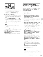
Страница 59: ...ay are hidden it becomes easy to adjust the picture To display the characters set the CHAR OFF button to off Aspect Marker Sets the aspect marker display Aspect Marker Sets whether or not to display the aspect marker when the MARKER button is pressed Off or On Aspect Mode Sets the aspect ratio of the aspect marker You can select from 16 9 15 9 14 9 13 9 4 3 2 39 1 2 35 1 1 85 1 1 66 1 1 896 1 or V...

Страница 60: ...ets the aspect ratio of the area marker 1 when Variable is selected in Aspect Mode Set to 1 00 1 to 3 00 1 1 78 1 Area Size Sets the size of the area marker 1 You can select from 80 88 90 93 Variable or Variable dot Width Sets the width of the area marker 1 when Area Size is set to Variable or Variable dot When Variable is selected Set to 050 to 100 080 When Variable dot is selected Set to 0360 to...

Страница 61: ...of the marker Set to 65 leftward to 65 rightward 00 V Position Sets the vertical position of the marker Set to 35 downward to 35 upward 00 Copy From Copies the other marker preset data Note Use the controller with software version 1 6 or higher to use the Copy From function Preset Value Copies other data in this monitor When the item is selected you can select from Marker1 Marker2 Marker3 Marker4 ...

Страница 62: ...display Blending Ratio Sets the blending ratio when two images are mixed Set to 000 Signal A disappears to 100 Signal B disappears 050 Pixel Zoom Setting Sets the pixel zoom Line Color Sets the boundary line color You can select from White white Red red Green green Blue blue Yellow yellow Cyan cyan or Magenta magenta or Black black Gamut Error Display Sets the gamut error display A zebra pattern i...

Страница 63: ... Set to 00000 to 65535 00000 Signal Level Sets the upper and lower lines of every signal to detect the gamut error SDI YCbCr 10bit Upper Limit upper limit Y 0000 to 1023 0983 Cb 0000 to 1023 1004 Cr 0000 to 1023 1004 Lower Limit lower limit Y 0000 to 1023 0020 Pb 0000 to 1023 0019 Pr 0000 to 1023 0019 SDI RGB 10bit Upper Limit upper limit G 0000 to 1023 0983 B 0000 to 1023 0983 R 0000 to 1023 0983...

Страница 64: ... signal analyzing function This item can be selected when the BKM 250TG is installed and is available for dual stream HD SDI signal input Horopter Check Changes the display mode of the left and right 3D video signals Left Selects the display mode of the left signal Normal Normal picture Black Displays a black signal the video signal is not displayed Mono Displays the video signal in monochrome mod...

Страница 65: ...selectable in the following cases When the input signal has no sync signal When Side by Side is set to On When Pixel Zoom is set to on When the HDMI DisplayPort computer signal is input The native scan is displayed regardless of the setting When a digital cinema signal 2048 1080 is input and the internal signal is displayed Native Scan is set to Off and the normal scan is displayed regardless of t...

Страница 66: ...ou can set the comb filter The comb filter is not set in the following cases When the internal signal is displayed When the captured frame is displayed Aperture Sets whether or not to function the aperture modification Off or On Off when the signal is displayed in Aspect Correction mode of the native display On when the signal is displayed in mode other than Aspect Correction of the native display...

Страница 67: ...he input signal has no sync signal When the internal signal is displayed When the HDMI DisplayPort computer signal is input When H Delay V Delay is set to On When Side by Side Wipe Butterfly or Blending is set to On When Pixel Zoom is set to on The area marker 1 may be displayed in an incorrect position when External Sync is On Area Marker 2 Sets whether or not to display the area marker 2 Off or ...

Страница 68: ...e blanking level of the Aspect Blanking the blanking outside the area of the aspect marker to 0 black level Off or On Notes The Aspect Blanking is not set to 0 black level in the following cases When the input signal has no sync signal When the internal signal is displayed When the HDMI DisplayPort computer signal is input When H Delay V Delay is set to On When Side by Side Wipe Butterfly or Blend...

Страница 69: ...e difference between the luminance of the left 3D video signal and that of the right signal Off or On This item is available for dual stream HD SDI signals Notes The Difference display cannot be set in the following cases When the option port number in which the BKM 250TG is installed is not selected in Input Port of the Channel Configuration menu When dual link display is used When the internal s...

Страница 70: ...e Horopter Check display cannot be set in the following cases When the option port number in which the BKM 250TG is installed is not selected in Input Port of the Channel Configuration menu When dual link display is used When the internal signal is displayed When a captured frame is displayed When Side by Side Wipe Butterfly or Blending is set to On The Horopter Check display may not be performed ...

Страница 71: ...dress is set to the displayed one Subnet Mask Sets the subnet mask 255 255 255 000 Note When the NETWORK switch is set to PEER TO PEER the subnet mask is set to 255 255 255 000 regardless of the display When the NETWORK switch is set to LAN the subnet mask is set to the displayed one Default Gateway Sets whether or not to set the default gateway Off or On Address Sets the address of the default ga...

Страница 72: ...3 Pin External Sync 4 Pin Mono 5 Pin Marker 6 Pin unused 7 Pin unused 8 Pin Tally You can change the assignment to the following functions for pins 1 to 8 The functions shown with item name only are the same as those assigned to the function buttons on the controller For details on these functions see Function Key page 82 of the Controller menu Parallel Remote 1 5 CH01 to 30 Selects a channel numb...

Страница 73: ... displayed for a while Off Not displayed Position Sets the display position for the channel number You can select from Top Left top left Top Center top center Top Right top right Bottom Left bottom left Bottom Center bottom center or Bottom Right bottom right CH Name Sets the display mode of the channel name Auto Disappears after being displayed for a while Off Not displayed Position Sets the disp...

Страница 74: ... menu page 82 of the Controller menu Time Code Sets the time code The setting is effective when the SDI signal is input Note As the time code is superimposed on the video signal the time code may be cut partially because of the scan mode setting of the monitor VITC LTC Sets the type of the time code You can select from VITC or LTC Position Sets the display position of the time code You can select ...

Страница 75: ...n Set Yes Apply the password No Not apply the password Date Time Yes Apply the password No Not apply the password Scan Mode Skip Yes Apply the password No Not apply the password Screen Saver Yes Apply the password No Not apply the password File Management Yes Apply the password No Not apply the password Controller Yes Apply the password No Not apply the password Key Protect Yes Apply the password ...

Страница 76: ... phase regardless of the setting of this item Monitor Upgrade Upgrades the monitor When the item is selected the screen for inputting the password is displayed After the 4 digit password is entered the current versions of Software Version Kernel Version FPGA Version and DisplayPort Version are displayed For the FPGA Version FPGA1 FPGA2 and FPGA CORE are displayed from left to right For the passwor...

Страница 77: ...cters Existed file name Select the file to save data The following message appears Overwrite this file OK To overwrite the data press the ENTER Ent button Cancel To cancel press the MENU button Note When a new name is entered the must not be used as the first character Copy From Copies the data Other Monitor Selects the data of other monitor Monitor ID Enter the ID number of the source monitor Whe...

Страница 78: ...ick are displayed When the file is selected the following message appears Delete this file OK To delete the data press the ENTER Ent button Cancel To cancel press the MENU button Data Maintenance Does maintenance the system data Back Up System Data Writes the data to the Memory Stick as the backup data The In progress x is displayed and x flashes during data writing It may take some time to write ...

Страница 79: ...s Option1 to Option4 Displays the type of input adaptor installed in Option1 to Option4 SD SDI When BKM 220D is installed Composite When BKM 227W is installed Component When BKM 229X is installed HD SD SDI When BKM 243HS or BKM 244CC is installed 3G HD SD SDI When BKM 250TG is installed Empty When the adaptor is not installed Unknown When non supported adaptor is installed When the item is selecte...

Страница 80: ...the monitor Format Displayed as Video Standard Sampling Structure Bit Depth Video Standard 3G DL HD SD Sampling Structure 422 YCbCr 444 YCbCr 444 RGB 444 XYZ Bit Depth 10 12 I PsF P Interlace PsF Progressive You can confirm the same information using the Status button on the controller For details see Displaying the Monitor Status Page page 98 HDMI DP Status Displays the signal information of the ...

Страница 81: ...sk Sets the subnet mask 255 255 255 000 Note When the NETWORK switch is set to PEER TO PEER the subnet mask is set to 255 255 255 000 regardless of the display When the NETWORK switch is set to LAN the subnet mask is set to the displayed one Default Gateway Sets whether or not to set the default gateway Off or On Address Sets the address of the default gateway no setting Cancel Cancels the changed...

Страница 82: ...button Authentication Sets whether or not to issue the authentication Disable or Enable This item cannot be selected when the monitor is controlled with BKM 15R or BVM A14F5 Community Sets the community name This item cannot be selected when the monitor is controlled with BKM 15R or BVM A14F5 When the item is selected you can enter the community name up to 20 characters public Initially public is ...

Страница 83: ...he trap band pass filter is selected When the displayed signal is NTSC PAL or PAL M this functions You can select the kind of the comb filter in the NTSC Comb Filter menu page 58 of the Auxiliary Setting menu Char Off The characters on the monitor screen hide during manual adjustment Color Temp You can access directly the Manual Adjust menu of the Color Temp Adj menu Status Various status informat...

Страница 84: ...e between the luminance of the left 3D video signal and that of the right signal is displayed Note Use the controller with software version 1 6 or higher to assign Difference to a function button of the controller Checkerboard The left and right 3D video signals are displayed in a checkerboard pattern L R Switch The left and right 3D video signals are displayed alternately by switching Note Use th...

Страница 85: ... the current versions of Software Version and Kernel Version are displayed For the password see Password page 74 of the System Configuration menu For details on upgrading the controller see Upgrading the Monitor and Controller on page 101 Software Upgrade Upgrades the software for the controller Kernel Upgrade Upgrades the kernel of the controller Menu Function and operation factory setting ...

Страница 86: ...factory setting Key Protect Sets the key protection On The button on the controller except the menu operation buttons and monitor selection buttons and the parallel remote do not function and other settings are not changeable Off Release the lock MENU Adjustment B Channel Configuration B Auxiliary Setting B Function Setting B System ConfigurationB File Management B System Status B Controller B Key...

Страница 87: ...inciple of operation in the interlace display mode However on this monitor the normal luminance is set by increasing the value of gain For this reason in the interlace display mode the range of the contrast adjustment is different from the normal level and the luminance may be reduced according to the setting of the contrast The picture is not displayed in interlace mode in the following cases Whe...

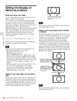
Страница 88: ... displayed Native Scan is set to Off and the normal scan is displayed regardless of the setting Display of the input signal system 2048 1080 When the input signal system is 2048 1080 and the native scan mode is selected you can display no display area of the left and right sides over the H size 1920 by sliding the picture with the PHASE knob of the controller You can restore the display position t...

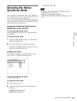
Страница 89: ...LED on the button is turned off 2 Press the SCAN button to select the scan mode Scan mode is changed to normal under and over scan mode by each press of the button Setting in the menu Set Scan Mode or Native Scan in the Function Switch menu page 65 of the Function Setting menu To set to the native scan mode Set Native Scan to On To select the scan mode 1 Set Native Scan to Off 2 Select Scan Mode t...

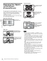
Страница 90: ...A and signal B are not the same signal format and signal system the pictures may not be displayed correctly The input of signal A is not changed in the multi display The internal signal is not displayed in the multi display The captured picture data is not used to display as signal A and signal B at the same time The signals are not displayed in the multi display mode when Pixel Zoom is set to on ...

Страница 91: ...display Set Side by Side Wipe Butterfly or Blending to Off in Function Switch menu page 65 of the Function Setting menu or set each function button of the controller to off Magnifying the Picture Pixel Zoom As part of the picture is magnified up to 8 times up to 4 times when the display magnification of the native scan is 2 without scaling processing this is convenient for confirming a minute of t...

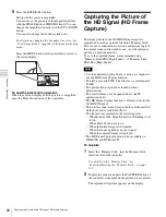
Страница 92: ...e we recommend using Memory Stick PRO High Speed or Memory Stick PRO Duo High Speed Use the controller with software version 1 6 or higher to use the HD Frame Capture function The file is saved in TIFF The file size is a maximum of 13 MB The picture file is captured or loaded without deterioration The saved file may not be opened due to the PC application used The HD Frame Capture function is effe...

Страница 93: ...nel 3 Set the marker preset data Marker1 to Marker5 to display in the Marker Preset menu page 54 of the Channel Configuration menu 4 Set the marker to display in the Marker Setting menu page 59 of the Function Setting menu for the preset data set in step 3 5 Select the marker mode Marker Aspect Marker Area Marker 1 Area Marker 2 Center Marker Aspect Marker Line Aspect Blanking Half or Aspect Blank...

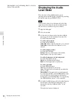
Страница 94: ...lected CH9 CH16 Selects when the channel 9 to 16 is selected To set the display position Set in the Position menu Bottom Displays at the bottom of the window Top Displays at the top of the window To set the transparency of the background Set in the Transparency menu Black Sets the background in black Half Sets the background in translucence To set the peak hold Set in the Peak Hold menu Off The pe...

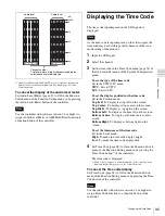
Страница 95: ...n for the time code Set in the Position menu Top Left To display it at top left on the screen Top Center To display at top center on the screen Top Right To display at top right on the screen Bottom Left To display at bottom left on the screen Bottom Center To display at bottom center on the screen Bottom Right To display at bottom right on the screen To set the luminance of the time code Set in t...

Страница 96: ...ly the video signal is not displayed Mono Displays the video signal in monochrome mode Red Displays only the red component of the video signal Blue Displays only the blue component of the video signal Flip H display The input 3D video signals whose left L or right R signal has been inverted horizontally by a half mirror type 3D rig are displayed as non inverted images Procedure 1 Input 3D video si...

Страница 97: ...l signal is displayed When a captured frame is displayed When Side by Side Wipe Butterfly or Blending is set to On The display of the 3D signal analyzing function may not be performed correctly when H Delay is set to On If saving is performed in HD Frame Capture when a 3D signal analyzing function other than Flip H is in use the function is deactivated and the normal display is restored Copying th...

Страница 98: ...he controller use the controller with software version 1 6 or higher Pixel Zoom is not set to on when the monitor status page is displayed 1 Press the Status button on the controller to set it to On Page 1 4 of STATUS display is displayed 2 Select the STATUS page you wish to view using the UP DOWN button on the controller You can select the page from among 1 4 2 4 3 4 and 4 4 For the contents of e...

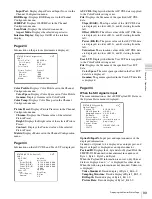
Страница 99: ...n order of R G and B starting from the left User LUT Displays whether the User LUT data is applied to the Color Profile setting or not File Displays the file name of the specified User LUT data Color Space The color space specified in the User LUT data file is displayed Gamma The gamma specified in the User LUT data file is displayed Page 4 4 When the SDI signal is input The same information as th...

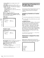
Страница 100: ... assigned to the function buttons can be displayed collectively Assigning a Function to a Function Button 1 Select the Function Key menu in the Controller menu 2 Select F1 to F16 button and then the function assigned on each button Assignable functions Scan Mode Native Scan 16 9 H Delay V Delay External Sync Comb Char Off Color Temp Status Aperture Mono Blue Only R Off G Off B Off Chroma Up Interl...

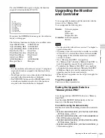
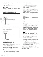
Страница 101: ...ernel Use the controller with software version 1 7 or higher to upgrade the monitor Upgrading of the software for the controller is available for version 1 11 or later of the software for the controller and upgrading of the controller kernel is available for version 1 2 or later Use a Memory Stick PRO for upgrading If a Memory Stick other than Memory Stick PRO is used the upgrading may not be exec...

Страница 102: ...ress the ENTER Ent button Upgrading starts The In progress x is displayed and x flashes during upgrading The x indication may stop flashing during upgrading but the data are being upgraded correctly Upgrading takes about 8 minutes for the software program about 2 minutes for the kernel about 3 minutes for FPGA data and about 2 minutes for DisplayPort data Do not remove the Memory Stick PRO from th...

Страница 103: ...ut the data are being upgraded correctly When version 1 2 or later of the software for the controller is upgraded When the upgrading starts the indicator lights as turning clockwise in the display window of the controller The indicator may stop during upgrading but the data are being upgraded correctly Upgrading takes about 2 minutes for the software program and about 2 minutes for the kernel Afte...

Страница 104: ...lue filter coefficient value etc Under scan 3 under scan Over scan Mask of 5 over scan portion in the normal scan Color temperature D55 D61 D65 D93 D Cine2 Setting possible in other color temperature 2 D Cine x 0 314 y 0 351 Standard luminance 100 cd m2 Preset1 to Preset5 48 cd m2 Preset D Cine 100 white signal input Color space color gamut ITU R BT 709 EBU SMPTE C D Cine3 E250 Native4 S GAMUT5 3 ...

Страница 105: ...2 W average power consumption in the default status Inrush current 1 Maximum possible inrush current at initial switch on Voltage changes caused by manual switching 53 A peak 17 A r m s 240V AC 2 Inrush current after a mains interruption of five seconds Voltage changes caused at zero crossing 39 A peak 6 A r m s 240V AC Operating temperature 0 C to 35 C 32 F to 95 F Recommended 20 C to 30 C 68 F t...

Страница 106: ...LIMITED TO COMPENSATION OR REIMBURSEMENT ON ACCOUNT OF FAILURE OF THIS UNIT OR ITS RECORDING MEDIA EXTERNAL STORAGE SYSTEMS OR ANY OTHER MEDIA OR STORAGE SYSTEMS TO RECORD CONTENT OF ANY TYPE Always verify that the unit is operating properly before use SONY WILL NOT BE LIABLE FOR DAMAGES OF ANY KIND INCLUDING BUT NOT LIMITED TO COMPENSATION OR REIMBURSEMENT ON ACCOUNT OF THE LOSS OF PRESENT OR PRO...

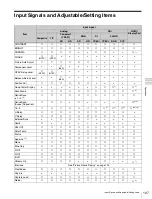
Страница 107: ...an Mode a a a a a a a a a a a 8 Native Scan 1 2 2 a a a a a a a a a a a Native Scan Aspect Correction a a a a a a 6 9 16 9 a a a a a a a a 3 a 4 a 4 a 5 9 10 H Delay a a a a a a a a a a V Delay a a a a a a a a a a External Sync a a a a Comb a Char Off a a a a a a a a a a a Color Temp a a a a a a a a a a a Status a a a a a a a a a a a Aperture 11 a a a a a a a a a a a Mono a a a a a a a a a a a Blu...

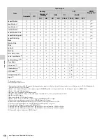
Страница 108: ...set to Off 11 For the operable input signal see Aperture Modification Frequency page 119 12 Sets when the SDI signal is input from BKM 250TG 13 Enabled when the SDI signal is input from a BKM 250TG with serial number 7100001 or higher 14 Enabled when the SDI signal is input from a BKM 250TG with serial number 7300001 or higher 15 Compatible with the dual stream HD SDI signal Aspect Marker a a a a ...

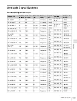
Страница 109: ...9 1 1920 1080 29 97PsF 1125 1080 30 1 001 Progressive 16 9 SMPTE 274M 1080 30PsF 1080 29 97PsF 2 2 39 1 1920 1080 24P 1125 1080 24 Progressive 16 9 SMPTE 274M 1080 24P 2 39 1 1920 1080 23 98P 1125 1080 24 1 001 Progressive 16 9 SMPTE 274M 1080 24P 1080 23 98P 2 2 39 1 1920 1080 25P 1125 1080 25 Progressive 16 9 SMPTE 274M 1080 25P 2 39 1 1920 1080 30P 1125 1080 30 Progressive 16 9 SMPTE 274M 1080 ...

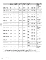
Страница 110: ... 16 9 SMPTE 296M 720 60P 720 59 94P 2 2048 1080 24PsF 1125 1080 24 Progressive 1 896 1 SMPTE 2048 SMPTE 428 2048 1080 24PsF 2 39 1 2048 1080 23 98PsF 1125 1080 24 1 001 Progressive 1 896 1 SMPTE 2048 SMPTE 428 2048 1080 24PsF 2048 1080 23 98PsF 2 2 39 1 2048 1080 24P 1125 1080 24 Progressive 1 896 1 SMPTE 2048 SMPTE 428 2048 1080 24P 2 39 1 2048 1080 23 98P 1125 1080 24 1 001 Progressive 1 896 1 S...

Страница 111: ...etup level 0 SD 487 59 94i a SMPTE 170M 7 5 PAL 576 50i a Rec ITU R BT 470 PAL M 487 59 94i a SECAM 576 50i a Analog Y C NTSC Setup level 0 SD 487 59 94i a 7 5 PAL 576 50i a PAL M 487 59 94i a SECAM 576 50i a Analog Component HD 1080 601 i a SMPTE 274M 1080 50i a 1080 241 PsF a 1080 25PsF a 1080 301 PsF a 1080 241 P a 1080 25P a 1080 301 P a 720 601 P a SMPTE 296M 720 50P a SD 576 50i a EBU N10 Co...

Страница 112: ...bCr 10bit HD 1920 1080 241 PsF a a a SMPTE 292M Dual link 4 4 4 YCbCr 10bit HD a 2 a SMPTE 372M RGB2 10bit YCbCr 12bit HD RGB2 12bit Single link 4 2 2 YCbCr 10bit HD 1920 1080 25PsF a a a SMPTE 292M Dual link 4 4 4 YCbCr 10bit HD a 2 a SMPTE 372M RGB2 10bit YCbCr 12bit HD RGB2 12bit Single link 4 2 2 YCbCr 10bit HD 1920 1080 301 PsF a a a SMPTE 292M Dual link 4 4 4 YCbCr 10bit HD a 2 a SMPTE 372M ...

Страница 113: ...2M Dual link 4 4 4 YCbCr 10bit HD a 2 a SMPTE 372M RGB2 10bit YCbCr 12bit HD RGB2 12bit Single link 4 2 2 YCbCr 10bit HD 1920 1080 601 i a a a SMPTE 292M Dual link 4 4 4 YCbCr 10bit HD a 2 a SMPTE 372M RGB2 10bit YCbCr 12bit HD RGB2 12bit Dual link 4 2 2 YCbCr 10bit HD 1920 1080 50P a 2 a Dual link 4 2 2 YCbCr 10bit HD 1920 1080 601 P a 2 a Single link 4 2 2 YCbCr 10bit HD 1280 720 241 P a a a SMP...

Страница 114: ... link 4 4 4 RGB2 10bit 2048 1080 25PsF a 2 a 12bit XYZ 12bit Dual link 4 4 4 RGB2 10bit 2048 1080 25P a 2 a 12bit XYZ 12bit Dual link 4 4 4 RGB2 10bit 2048 1080 301 PsF a 2 a 12bit XYZ 12bit Dual link 4 4 4 RGB2 10bit 2048 1080 301 P a 2 a 12bit XYZ 12bit Signal format Matrix data setting area Sygnal system Standard SDI input BKM 220D BKM 227W BKM 229X BKM 243HS 244CC BKM 250TG Standard ...

Страница 115: ...5P a a SMPTE 425 AB 4 4 4 RGB2 10bit 4 4 4 YCbCr 12bit HD 4 4 4 RGB2 12bit Single link 4 4 4 YCbCr 10bit HD 1920 1080 301 P a a SMPTE 425 AB 4 4 4 RGB2 10bit 4 4 4 YCbCr 12bit HD 4 4 4 RGB2 12bit Single link 4 4 4 YCbCr 10bit HD 1920 1080 50i a a SMPTE 425 AB 4 4 4 RGB2 10bit 4 4 4 YCbCr 12bit HD 4 4 4 RGB2 12bit Single link 4 4 4 YCbCr 10bit HD 1920 1080 601 i a a SMPTE 425 AB 4 4 4 RGB2 10bit 4 ...

Страница 116: ...80 720 601 P a a SMPTE 425 AB 4 4 4 RGB2 10bit Single link 4 4 4 RGB2 10bit 2048 1080 241 PsF a a SMPTE 425 AB 4 4 4 12bit 4 4 4 XYZ 12bit Single link 4 4 4 RGB2 10bit 2048 1080 241 P a a SMPTE 425 AB 4 4 4 12bit 4 4 4 XYZ 12bit Single link 4 4 4 RGB2 10bit 2048 1080 25PsF a a SMPTE 425 AB 4 4 4 12bit 4 4 4 XYZ 12bit Single link 4 4 4 RGB2 10bit 2048 1080 25P a a SMPTE 425 AB 4 4 4 12bit 4 4 4 XYZ...

Страница 117: ... 250 16 9 1920 1080 50i 74 250 16 9 CEA 861 2 39 1 SD 720 1440 3 576 50i7 27 000 4 3 16 9 CEA 861 HD 1920 1080 601 P 148 5001 16 9 CEA 861 2 39 1 1920 1080 50P 148 500 16 9 CEA 861 2 39 1 1920 1080 241 P 74 2501 16 9 CEA 861 2 39 1 1920 1080 25P 74 250 16 9 CEA 861 2 39 1 1920 1080 301 P 74 2501 16 9 CEA 861 2 39 1 2048 1080 241 P 74 2501 1 896 1 2 39 1 2048 1080 25P 74 250 1 896 1 2 39 1 2048 108...

Страница 118: ...nals are referred to as the HDMI DisplayPort computer signals 5 The HDMI signal does not support the RGB YCbCr 4 4 4 6bit signal 6 The DisplayPort signal does not support the RGB YCbCr 4 4 4 12bit signal 7 The DisplayPort signal does not support this signal system The quantization level of the HDMI DisplayPort input signal is set in the RGB Range menu page 55 The aspect ratio of the HDMI input sig...

Страница 119: ...z 1080 601 i 301 PsF 25 MHz 25 MHz 1080 301 P 25 MHz 25 MHz 720 241 P 25 MHz 720 25P 25 MHz 720 301 P 25 MHz 720 50P 25 MHz 25 MHz 720 601 P 25 MHz 25 MHz 2048 1080 241 PsF 25 MHz 2048 1080 241 P 25 MHz 2048 1080 25PsF 25 MHz 2048 1080 25P 25 MHz 2048 1080 301 PsF 25 MHz 2048 1080 301 P 25 MHz 1080 50P 50 MHz 1080 601 P 50 MHz HDMI DisplayPort 640 480 601 P 10 MHz 720 480 601 P 10 MHz 1280 720 601...

Страница 120: ...annot be input or the aperture modification does not operate for that signal even if it is input 1920 1080 25P 25 MHz 1920 1080 301 P 25 MHz 2048 1080 241 P 25 MHz 2048 1080 25P 25 MHz 2048 1080 301 P 25 MHz 2048 1080 601 P 50 MHz 2048 1080 50P 50 MHz 2048 1080 481 P 50 MHz Signal system Serial digital input Analog input HDMI DisplayPort input SD SDI 3G HD SDI Composite Y C Component YPbPr RGB Com...

Страница 121: ...1862 779 1829 765 960 402 1920 1080 25P 16 9 1920 1080 1920 1080 1862 1048 1829 1029 960 540 2 39 1 1920 803 1862 779 1829 765 960 402 1920 1080 301 P 16 9 1920 1080 1920 1080 1862 1048 1829 1029 960 540 2 39 1 1920 803 1862 779 1829 765 960 402 1920 1080 50i 16 9 1920 1080 1920 1080 1862 1048 1829 1029 960 540 2 39 1 1920 803 1862 779 1829 765 960 402 1920 1080 601 i 16 9 1920 1080 1920 1080 1862...

Страница 122: ...9 960 540 2 39 1 1920 803 1862 779 1829 765 960 402 720 1440 2 576 50i3 4 3 720 576 1440 1152 1536 1152 1440 1080 1397 1048 1371 1029 960 720 16 9 2048 1152 1920 1080 1862 1048 1829 1029 960 540 1920 1080 601 P 16 9 1920 1080 1920 1080 1862 1048 1829 1029 960 540 2 39 1 1920 803 1862 779 1829 765 960 402 1920 1080 50P 16 9 1920 1080 1920 1080 1862 1048 1829 1029 960 540 2 39 1 1920 803 1862 779 18...

Страница 123: ...ed in the 1080I PsF menu of the Channel Configuration menu Signal system Progressive Interlace Display frame rate Hz Display frame rate Hz 720 576 50i 50 50 1440 576 50i2 50 50 720 487 59 94i 59 94 59 94 1440 487 59 94i2 59 94 59 94 1920 1080 241 PsF 721 481 3 1920 1080 25PsF 75 503 1920 1080 301 PsF 601 601 3 1920 1080 241 P 721 1920 1080 25P 75 1920 1080 301 P 601 1920 1080 50i 50 504 1920 1080 ...

Страница 124: ...1 P 601 720 480 601 P 601 1280 720 601 P 601 1920 1080 601 i 601 601 720 1440 2 480 601 i3 601 601 720 576 50P 50 1280 720 50P 50 1920 1080 50i 50 50 720 1440 2 576 50i3 50 50 1920 1080 601 P 601 1920 1080 50P 50 1920 1080 241 P 721 1920 1080 25P 75 1920 1080 301 P 601 2048 1080 241 P 721 2048 1080 25P 75 2048 1080 301 P 601 2048 1080 601 P 601 2048 1080 50P 75 2048 1080 481 P 481 800 600 60P SVGA...

Страница 125: ...tive Scan Native Scan Mode 1 1920 1080 1920 1080 2048 1080 1280 720 720 576 720 487 Displayed by sliding the picture with the PHASE knob of the controller Native Scan Mode 2 Native Scan Mode Aspect Correction Aspect 4 3 Native Scan Mode Aspect Correction Aspect 16 9 Scan mode Input signal system and scan mode image 720 487 1440 487 720 576 1440 576 Displayed by sliding the picture with the UP DOWN...

Страница 126: ...gnal system and scan mode image 1920 1080 1280 720 2048 1080 720 576 720 487 1440 576 1440 487 1920 1080 2048 1080 720 576 720 487 1440 576 1440 487 1920 1080 1280 720 2048 1080 720 576 720 487 1440 576 1440 487 1920 1080 2048 1080 720 576 720 487 1440 576 1440 487 1920 1080 1280 720 2048 1080 720 576 720 487 1440 576 1440 487 5 mask portion Aspect 2 39 1 Aspect 4 3 Scan mode Input signal system a...

Страница 127: ...d the DisplayPort signal is selected as signal B The multi display with an HDMI signal and a DisplayPort signal is not possible The phase of signal B in the multi display slips The signal is not genlocked Genlock signal A and signal B to use the wipe mode and blending mode The signal input from BKM 227W or BKM 229X is not displayed correctly The auto chroma phase matrix adjustment has not been per...

Страница 128: ...ction is assigned in the Parallel Remote menu of the System Configuration menu to On page 72 Select Error Notify Clear in the Function Switch menu of the Function Setting menu page 69 The zebra pattern does not go off A gamut error is detected Set Gamut Error Display to Off in the Gamut Error Display menu of the Function Setting menu page 62 An Over Range error is detected The zebra pattern is set...

Страница 129: ... the controller is attached with the BKM 37H When the tilt unit is removed from the BKM 37H Front Side Bottom 60 2 3 8 254 10 508 20 226 9 576 22 3 4 424 16 3 4 551 21 3 4 331 13 1 8 34 4 1 3 8 148 5 7 8 55 2 1 4 40 1 5 8 15 19 32 226 9 100 4 200 7 7 8 M4 1 334 2 13 1 4 269 7 10 5 8 59 7 2 3 8 467 7 18 1 2 266 10 1 2 30 1 3 16 230 9 1 8 4 M5 6 Ø8 489 8 19 3 8 30 1 3 16 195 7 3 4 30 1 3 16 ...

Страница 130: ...H Front Side Bottom When the controller is attached with the BKM 38H Front Side Bottom 285 7 11 1 4 75 7 3 483 7 19 1 8 266 10 1 2 30 1 3 16 4 M5 6 Ø8 230 9 1 8 489 8 19 3 8 30 1 3 16 195 7 3 4 30 1 3 16 576 22 3 4 469 6 19 5 8 271 6 10 3 4 61 6 2 1 2 266 10 1 2 30 1 3 16 ...

Страница 131: ...he Memory Stick in the wrong way may damage it Insert only the Memory Stick into the Memory Stick insertion slot Attempting to insert other objects into the Memory Stick insertion slot may damage the product To eject the Memory Stick Notes on Memory Stick Available types of Memory Stick Memory Stick Memory Stick PRO Memory Stick Duo Memory Stick PRO Duo and Memory Stick Micro are used for the BKM ...

Страница 132: ...Memory Stick Duo Memory Stick PRO Duo Memory Stick Micro and M2 duo size adaptor should be kept away from small children to prevent them from accidentally swallowing it If the Memory Stick Micro attached to the M2 adaptor is attached to the Memory Stick Duo adaptor and inserted in the slot the Memory Stick Micro may not function Up to 1000 files can be memorized in one Memory Stick When more than ...

Страница 133: ...Marker 2 61 Function Setting menu 67 Function Setting menu ASC CDL 53 Channel Configuration menu 57 Auxiliary Setting menu Aspect Blanking Black 68 Function Setting menu Aspect Blanking Half 68 Function Setting menu Aspect Marker 59 Function Setting menu 67 Function Setting menu Aspect Marker Line 68 Function Setting menu Audio CH 74 System Configuration menu Audio Level Meter 69 Function Setting ...

Страница 134: ...54 Channel Configuration menu Contrast Bright Hold 47 Adjustment menu Controller 81 Controller menu Controller Status 80 System Status menu Controller Upgrade 85 Controller menu Copy From 45 Adjustment menu 47 Adjustment menu 56 Channel Configuration menu 61 Function Setting menu 77 File Management menu D Data Maintenance 78 File Management menu Date Time 75 System Configuration menu Default CH 73...

Страница 135: ...t menu H Shift Offset 54 Channel Configuration menu HDMI Auto 51 Channel Configuration menu HDMI DisplayPort Auto 52 Channel Configuration menu 55 Channel Configuration menu HDMI DP Status 80 System Status menu Horopter Check 64 Function Setting menu 70 Function Setting menu I Input Detection 63 Function Setting menu Input Information 73 System Configuration menu Input No 51 Channel Configuration ...

Страница 136: ...inal Value 47 Adjustment menu OSD Level 74 System Configuration menu OSD Notification 63 Function Setting menu OSD Notification Reset 63 Function Setting menu Over Range 74 System Configuration menu P P P Setting 61 Function Setting menu Panel On Time 80 System Status menu Parallel Remote 72 System Configuration menu Password 74 System Configuration menu Peak Hold 74 System Configuration menu Peak...

Страница 137: ...ignal 47 Adjustment menu Signal Level 63 Function Setting menu 64 Function Setting menu SNMP Setting 81 Controller menu Software Upgrade 76 System Configuration menu 85 Controller menu Software Version 80 System Status menu Standby Mode 73 System Configuration menu Status 45 Adjustment menu Sync Mode 51 Channel Configuration menu System Configuration 71 System Configuration menu System Status 79 S...

Страница 138: ......

Страница 139: ... for use by the purchasers of the equipment described in this manual Sony Corporation expressly prohibits the duplication of any portion of this manual or the use thereof for any purpose other than the operation or maintenance of the equipment described in this manual without the express written permission of Sony Corporation ...

Страница 140: ...Sony Corporation BVM E250 WW 4 274 954 14 1 Printed in Japan 2012 03 08 2011 ...

Отзывы: