background image

!

!


Power 24 VAC, Class 2 Only

GENERAL INSTRUCTIONS:

Tools Required:  .100" Flat Head Screwdriver
 

Phillips Head Screwdriver


Slotted Head Screwdriver

Add thread 

sealing tape

Be sure the bracket is properly and securely mounted 
to a supporting structure capable of rigidly holding the 
weight of the entire unit.  

1


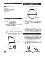
Using the security tool provided, open the housing by 
loosening the (3) captive security screws located on the 
housing ring next to the lower clear dome (Figure 2). 

Loosen three 

security screws 

holding dome 

2


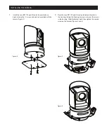
Install the pan/tilt unit quick-release bracket.  It is 
recommended that this be done before installing the housing.  
On the next page are instructions for mounting the camera 
into the housing.

3


It is recommended that the camera be installed at this time.

         Connect to the quick-release bracket as shown and
         secure per manufacturer directions.

4


Clean the inside of the dome, with the text-wipe provided.
Reattach the housing dome and secure the (3) captive screws.  
Do not overtighten the screws.  Tighten only to the point at 
which the gap between the ring and the housing top closes. 


ELECTRICAL SPECIFICATIONS 

1


Carefully remove the housing from the packaging material.

          Check to be sure all parts are present.

2

        This unit includes a 1½" NPT housing coupling that can 

           be used with a standard 1½"" NPT pipe.  The housing can 
           be used with other brackets designed with 1½"" male pipe
           threads, such as the UNI-WMA1 wall mount bracket.

3

        Attach the housing coupling to the bracket or pendant pipe 

           (Figure 1).
           

NOTE:

  Pipe threads should be clean and rust free.   Use a 

                          sealer (such as Teflon™ tape or silicone sealer) on 
                          the threads. 

PREPARING PENDANT MOUNT MODEL

Figure 1

INSTALLING QUICK RELEASE BRACKET AND 
PAN/TILT CAMERA ASSEMBLY (ALL MODELS)

Figure 2

INSTALLING THE HOUSING ASSEMBLY

For BRCSDP16

53 watts at 24 VAC (heater and blower)
30 watts at 24 VAC (camera)
Input Connectors:  
          BNC 
          (2) screw-down connectors
          RJ-45 Connector

1

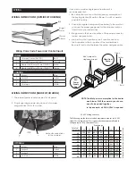
      Mount the housing assembly to the mounting bracket and  

         housing coupling.  A safety cable is included with the housing 
         to temporarily hold it while making wiring connections.  Loop 
         the safety cable over one of the set screws on the housing 
         coupling and make the appropriate connections using the (2) 
         screw-down connectors supplied.

2

      Undo the safety cable and twist the housing onto the housing

         coupling.  Secure all (3) setscrews provided on the housing 
         coupling (Figure 3).

3

      Clean the outside of the dome.

Twist and 

Secure

Figure 3

Heater and Blower Only

Содержание BRCSDP16

Страница 1: ...E HOUSING Installation and Operation Instructions for the following model BRCSDP16 CONTENT OF BOX 1 Housing 1 Supplied Parts 1 Power Connector Heater blower 1 Toolhead Driver 1 Operation Instruction Manual 81 IN6584 03082011 ...

Страница 2: ... remove the housing from the packaging material Check to be sure all parts are present 2 This unit includes a 1 NPT housing coupling that can be used with a standard 1 NPT pipe The housing can be used with other brackets designed with 1 male pipe threads such as the UNI WMA1 wall mount bracket 3 Attach the housing coupling to the bracket or pendant pipe Figure 1 NOTE Pipe threads should be clean a...

Страница 3: ...e power connector yellow and green wire 4 Jumper from the 1st position to the 3 rd position and from the 2nd position to the 4th position of the terminal block Be careful not to short between the yellow and green wires 22 250 120 89 65 44 35 29 25 31 19 17 16 14 13 12 20 400 180 141 90 70 56 47 40 34 31 28 25 23 21 20 18 600 300 225 130 112 90 75 64 55 50 45 41 37 34 32 16 960 480 358 225 179 143 ...

Страница 4: ...crews and washers provided with the camera Figure 4 Figure 4 2 Place the Sony BRC700 pan tilt and quick release bracket in the housing sliding the three open screw slots over the screws in the housing Slide the bracket back then tighten the captive screw on the bracket Figures 5 and 6 Figure 5 Figure 6 ...

Страница 5: ...he foregoing could result in the unit separating from the support structure and falling with resultant damages or injury to anyone or anything struck by the falling unit IMPORTANT SAFEGUARDS SAFETY PRECAUTIONS UNPACKING SERVICE CAUTION RISK OF ELECTRIC SHOCK DO NOT OPEN CAUTION TO REDUCE THE RISK OF ELECTRIC SHOCK DO NOT REMOVE COVER OR BACK NO USER SERVICEABLE PARTS INSIDE REFER SERVICING TO QUAL...

Страница 6: ...ine serves as the geometric center line used to insure proper camera placement It is not typically seen by the camera However Sony RZ series PTZ cameras are able to tilt up above the horizon to 25 this wide range of tilt motion at a wide angle view may cause this line to be captured in the image Warranty For warranty information on this and other Sony Security Systems Products please visit http pr...

Отзывы: