


9
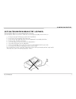
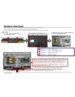
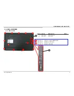
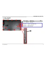
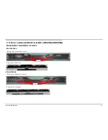
SERVICE POSITION
<KDL-32R330B>
2. Remove all screws on the Rear Cover to
Bezel & Main Board & Bracket (thirteen screws)
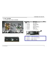
1.
Remove all screws on the Stand
to main unit (four screws)
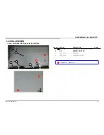
3. After removing rear cover , lie down the main unit
to a surface for following test/repair.
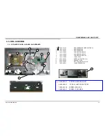
2-580-603-01 SCREW, +PSW M4X16
2-345-219-11 +B IB 3X-- CM3 (SCREW M3X6)
2-580-638-01 SCREW, +BVTP2 4X8
7-682-903-19 SCREW +PWH 3X6
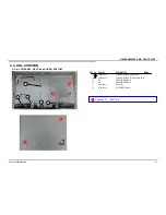
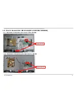
As for this model, the bottom of rear cover is installed between the stand assy and the panel.
Therefore according to the following procedure when performing adjustment and operation check after the part replacement.
Note:
Remove rear cover, then assemble the stand to main unit. This
will cause the stand with main unit fit closely, scratch or deformation
may occurred easily on the stand or bezel deco.
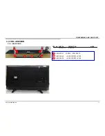
Attention:
This photo is based on Sony criteria for appearing standing the
main unit after removing back cover and assembling the stand. But
considering mechanical design of this models and normal service process,
it is not recommended to keep main unit standing by this status for
repairing/testing at repair center.
Please pay attention for avoiding
possible scratch/deformation occurred.
KDL-32R330B/40R380B
Содержание Bravia KDL-32R330B
Страница 8: ...8 SELF DIAGNOSIS FUNCTION This model doesn t support Self Diagnosis Function KDL 32R330B 40R380B ...
Страница 32: ...32 SEC 3 DIAGRAMS AND CHASSIS STRUCTURE 3 1 BLOCK DIAGRAM 3 1 1 KDL 32R330B 40R380B KDL 32R330B 40R380B ...
Страница 36: ...36 END 9 888 163 01 Sony Corporation KDL 32R330B 40R380B ...