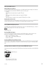
• When connecting to the engineer line:
Set the INTERCOM switch to ENG.
• When connecting only a camera:
Set the INTERCOM switch to PRIV.
When this position is set, the intercom from outside is cut and the system consists of the intercom and camera.
Note
When INTERCOM CH in INTERCOM (C07) of the CCU CONFIGURATION menu is set to 1CH, the INTERCOM
switch on the front panel of this unit and the camera are fixed to the producer line regardless of the setting.
2-3-2.
Microphone Setting
This unit can receive two independent microphone lines (MIC1 and MIC2) from the video camera HDC2000 series and
output them.
Remote Controlling Microphone Input Amplifier Gain
Remote control using the menu setting
When the MIC REMOTE connector on the rear panel is open or pins 8 (MIC1) and 15 (MIC2) of the MIC REMOTE
connector are at a high level, Adjusting the CAM MIC GAIN with MIC/AUDIO (C06) of the CCU CONFIGURATION
menu.
Setting values: 20, 30, 40, 50, 60 dB (Factory setting: 60 dB)
Adjusting the microphone input gain using the MIC REMOTE connector
The microphone input amplifier gain control is enabled or disabled by pins 8 and 15 of the MIC REMOTE connector
on the rear panel.
Furthermore, the microphone input amplifier gain can be set by pins 5 to 7 and 12 to 14.
When MIC REMOTE in OTHERS (M04) of the MAINTENANCE menu is set to MIC1 & 2 or MIC+NETWORK, the
MIC1 gain and MIC2 gain can be set by pins 5 to 7 and the microphone input amplifier gain can be set at the same time.
When MIC REMOTE is set to MIC1 or MIC2, the MIC1 gain and MIC2 gain can be set independently. Set the MIC1
gain by pins 5 to 7, and the MIC2 gain by pins 12 to 14.
Setting the microphone input control of the video camera
Pin No.
Microphone connector
8
15
MIC IN CH-1
MIC IN CH-2
L
L
ON
ON
L
H
ON
OFF
H
L
OFF
ON
H
H
Set with CAM MIC GAIN of MIC/AUDIO (C05)
Setting the microphone input gain of the video camera
Pin No.
Gain
7
6
5
H
H
H
60 dB
L
H
H
50 dB
H
L
H
40 dB
L
L
H
30 dB
H
H
L
20 dB
HDCU2500
2-9
Содержание 10001
Страница 6: ......
Страница 12: ......
Страница 14: ......
Страница 25: ...1 5 Outside Dimensions HD CAMERA CONTROL UNIT 1 5 200 1 3 7 1 4 7 2 1 9 Unit mm HDCU2500 1 11 ...
Страница 118: ......
Страница 130: ...Harness BOARD1 and Harness BOARD2 Upper Side Harness BOARD1 Harness BOARD2 Lead pin RE 274 board HDCU2500 4 12 ...
Страница 148: ......
Страница 161: ...B 1000 7 mVp p 75 Ω termination EN 159A 159B board Side A A B C D E F G H J 1 2 3 4 5 RV305 B A NTSC PAL HDCU2500 5 13 ...
Страница 162: ......
Страница 264: ......
Страница 357: ...Section 9 Board Layouts ADO 12 CN1 CN2 CN5 A SIDE SUFFIX 11 ADO 12 B SIDE SUFFIX 11 ADO 12 HDCU2500 9 1 ...
Страница 368: ...EN 159A EN 159B The location is described at the end in this section A SIDE SUFFIX 11 EN 159B EN 159A HDCU2500 9 12 ...
Страница 369: ... B SIDE SUFFIX 11 EN 159B EN 159A HDCU2500 9 13 ...
Страница 374: ...PS 778D00 B SIDE SUFFIX 11 HDCU2500 9 18 ...
Страница 392: ...HDCU2500 SY HDCU2500 CE J E 9 968 889 01 Sony Corporation Printed in Japan 2012 1 08 2012 ...


