


Setting Headset Microphone
Setting intercom microphone
Set the INCOM MIC in FRONT INCOM (C08) of the CCU CONFIGURATION menu according to the microphone
type of the headset to be connected to the INTERCOM connector on the front panel.
• CARBON:
When using a carbon microphone (power supplied, 20 dB gain)
• ECM:
When using a electric condenser microphone (power supplied, 40 dB gain)
• DYNAMIC:
When using a dynamic microphone (no power supplied, 60 dB gain) (Factory setting)
Adjusting the side tone level
Adjust the sidetone volume of the headset connected to the INTERCOM connector on the front panel with SIDE TONE
in FRONT INCOM (C08) of the CCU CONFIGURATION menu according to the headset to be used.
Setting PGM Audio Signal Input Level
Set the PGM1 INPUT and PGM2 INPUT in INTERCOM (C07) of the CCU CONFIGURATION menu to –20 dBu , 0
dBu, or +4 dBu according to each level of audio 1 and 2 of the system.
Note
Factory setting: 0 dBu
Selecting PGM Audio Signal
Select the PGM audio signal of the headset connected to the INTERCOM connector on the front panel to user’s
preference level with PGM SEL in FRONT INCOM (C08) of the CCU CONFIGURATION menu.
• PGM 1: To select PGM1 (Factory setting)
• PGM1 + PGM2: To select PGM1 and PGM2 mixed
• PGM2: To select PGM2
Adjusting PGM Audio Signal Mixing Volume
Adjust the PGM audio signal mixing volume of the headset connected to the INTERCOM connector on the front panel
to user’s preference level with PGM1 LVL/PGM2 LVL in FRONT INCOM (C08) of the CCU CONFIGURATION
menu.
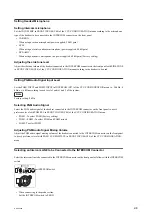
Selecting an Intercom LINE to be Connected to the INTERCOM Connector
Select the intercom line to be connected to the INTERCOM connector on the front panel as follows with the INTERCOM
switch.
INTERCOM switch
• When connecting to the producer line:
Set the INTERCOM switch to PROD.
HDCU2500
2-8
Содержание 10001
Страница 6: ......
Страница 12: ......
Страница 14: ......
Страница 25: ...1 5 Outside Dimensions HD CAMERA CONTROL UNIT 1 5 200 1 3 7 1 4 7 2 1 9 Unit mm HDCU2500 1 11 ...
Страница 118: ......
Страница 130: ...Harness BOARD1 and Harness BOARD2 Upper Side Harness BOARD1 Harness BOARD2 Lead pin RE 274 board HDCU2500 4 12 ...
Страница 148: ......
Страница 161: ...B 1000 7 mVp p 75 Ω termination EN 159A 159B board Side A A B C D E F G H J 1 2 3 4 5 RV305 B A NTSC PAL HDCU2500 5 13 ...
Страница 162: ......
Страница 264: ......
Страница 357: ...Section 9 Board Layouts ADO 12 CN1 CN2 CN5 A SIDE SUFFIX 11 ADO 12 B SIDE SUFFIX 11 ADO 12 HDCU2500 9 1 ...
Страница 368: ...EN 159A EN 159B The location is described at the end in this section A SIDE SUFFIX 11 EN 159B EN 159A HDCU2500 9 12 ...
Страница 369: ... B SIDE SUFFIX 11 EN 159B EN 159A HDCU2500 9 13 ...
Страница 374: ...PS 778D00 B SIDE SUFFIX 11 HDCU2500 9 18 ...
Страница 392: ...HDCU2500 SY HDCU2500 CE J E 9 968 889 01 Sony Corporation Printed in Japan 2012 1 08 2012 ...


