background image


Working Instruction

Mechanical


1209-0972 Rev 2 

34(64) 


3.21 Co-Brand Label 


Removal 


No Disassembly needed! 

Use a Dentist Hook to remove the Co-Brand label 

Installation 


Use your fingers to attach the Co-Brand Label 


No Reassembly needed!


Company Internal 

©

 Sony Ericsson Mobile Communications AB


Содержание W890

Страница 1: ...ame Sub Assembly PWB 17 3 Replacements 19 3 1 Battery Cover Battery 20 3 2 Front Cover Assembly Complete 20 3 3 Rear Cover Assembly 20 3 4 Ant Main PIFA 20 3 5 Camera Flex Module 20 3 6 Display 2 02A SI TFT 20 3 7 Key Flex Module 20 3 8 Frame Sub Assembly PWB 20 3 9 Screw Cap 21 3 10 QCIF VGA Camera 22 3 11 Cap GrommetF 24 3 12 Keyboard Main 25 3 13 RF Cap 26 3 14 Key On Off 27 3 15 SIM M2 Flex Mo...

Страница 2: ...pixel CMOS 46 3 34 Cap Grommet CamR 48 3 35 Frame Sub Assembly Camera 49 3 36 Cushion 0 0 mm System conn 51 3 37 Liquid Intrusion Indicator 52 4 Reassembly 54 4 1 Overview 54 4 1 1 Frame Sub Assembly PWB and Key Flex Module 55 4 1 2 Display 2 02A SI TFT 56 4 1 3 Camera Flex Module 57 4 1 4 Main PWB 59 4 1 5 Ant Main PIFA 60 4 1 6 Rear Cover Assembly 61 4 1 7 Front Cover Assembly Complete 62 4 1 8 ...

Страница 3: ...Working Instruction Mechanical 1209 0972 Rev 2 3 64 1 Introduction Company Internal Sony Ericsson Mobile Communications AB ...

Страница 4: ...emoval Tool 3Mpixel NTZ1121077 Camera Tool NTZ 112 590 Plectrum SVC Repair STANDARD TOOLS Standard tools text Dentist hook ESD tweezers Nylon Pointer ESD EQUIPMENT Protect the phone from ESD damages whenever it has been opened by using ESD wristband ESD gloves LABEL EQUIPMENT The following special equipment is required when replacing or installing a new label Hot air flow solder station Zebra prin...

Страница 5: ...E THE DENTIST HOOK TWEEZERS OPENING TOOLS GUITAR PICK ETC TO AVOID SCRATCHES OR DAMAGES TO THE EXTERIOR AND INTERIOR PARTS OF THE PHONE BE CAREFUL NOT TO DAMAGE ANY CONTACT SPRINGS REMEMBER TO REMOVE THE PROTECTION FOILS ON NEW PARTS SUCH AS THE FRONT COVER AND LCD NEVER TOUCH THE DISPLAY GLASS USE AIR BLOW EQUIPMENT TO KEEP THE FRONT WINDOW AND DISPLAY MODULE DUST FREE 1 3 Adhesives Use a dentist...

Страница 6: ...out in order to disassemble the phone as far as needed before returning to Replacements for the actual replacement Start DISASSEMBLY REASSEMBLY Contents page REPLACEMENTS Done 2 1 Overview The disassembly is done in the following sequence 1 Battery Cover Battery 2 Front Cover Assy Complete 3 Rear Cover Assembly 4 Ant Main PIFA 5 Main PWB 6 Camera Flex Module 7 Display 2 02A SI TFT 8 Key Flex Modul...

Страница 7: ...chanical 1209 0972 Rev 2 7 64 2 1 1 Battery Cover Battery Use your fingers to unsnap the two locks on the side of the phone Lift up the battery cover Remove the Battery Company Internal Sony Ericsson Mobile Communications AB ...

Страница 8: ... Cover Assy Complete Use a dentist hook to remove the two Screw caps Use Torx bit no 6 to remove the four screws Use a guitar pick to unsnap the Front Cover Continue on the other side to unsnap the Front Cover Company Internal Sony Ericsson Mobile Communications AB ...

Страница 9: ...Working Instruction Mechanical 1209 0972 Rev 2 9 64 Disassembly Instruction continued Remove the Front Cover Assembly Complete Company Internal Sony Ericsson Mobile Communications AB ...

Страница 10: ... 64 2 1 3 Rear Cover Assembly Locate the four snap hooks Use a guitar pick to unhook the Rear Cover Assembly Use a guitar pick to unhook the Rear Cover Assembly Flip over the Rear Cover Assembly Company Internal Sony Ericsson Mobile Communications AB ...

Страница 11: ...Working Instruction Mechanical 1209 0972 Rev 2 11 64 Disassembly Instruction continued Use a Nylon Pointer to detach the Rear Cover Assembly Company Internal Sony Ericsson Mobile Communications AB ...

Страница 12: ...Working Instruction Mechanical 1209 0972 Rev 2 12 64 2 1 4 Ant Main PIFA Use your fingers to unsnap the Antenna Remove the Antenna Main PIFA Company Internal Sony Ericsson Mobile Communications AB ...

Страница 13: ...l 1209 0972 Rev 2 13 64 2 1 5 Main PWB Use a Plectrum to unsnap the Main PWB Use your fingers to flip over the Main PWB Use a Nylon Pointer to detach the three BtB connectors Company Internal Sony Ericsson Mobile Communications AB ...

Страница 14: ...ule Use the JCIS bit to remove the two screws Use a Flex film assembly tool to detach the pads Use a Flex film assembly tool to detach the Camera Flex Module Use a Flex film assembly tool to detach the Camera Flex Module Company Internal Sony Ericsson Mobile Communications AB ...

Страница 15: ...Working Instruction Mechanical 1209 0972 Rev 2 15 64 Disassembly Instruction continued Remove the Camera Flex Module Company Internal Sony Ericsson Mobile Communications AB ...

Страница 16: ...nstruction Mechanical 1209 0972 Rev 2 16 64 2 1 7 Display 2 02A SI TFT Use a pair of tweezers to unsnap the display Use your fingers to remove the display Company Internal Sony Ericsson Mobile Communications AB ...

Страница 17: ... 8 Key Flex Module and Frame Sub Assembly PWB Use a dentist hook to unsnap the vibrator Use a Flex film assembly tool to detach the camera pad Use a Flex film assembly tool to detach the key flex module Company Internal Sony Ericsson Mobile Communications AB ...

Страница 18: ...ruction Mechanical 1209 0972 Rev 2 18 64 Disassembly Instruction continued Use a Flex film assembly tool to remove the Key Flex Module Frame Sub Assembly PWB Company Internal Sony Ericsson Mobile Communications AB ...

Страница 19: ...ication of the instructions you have to carry out in order to disassemble the phone as far as needed before the actual replacement Go back to this Replacements section and carry out the instruction The instruction usually ends by directing you to the Reassembly section with a specification of the instructions you have to carry out in order to reassemble the phone Start DISASSEMBLY REASSEMBLY Conte...

Страница 20: ... the 2 1 1 2 1 4 Disassembly instructions Replace Ant Main PIFA Follow the 4 1 5 4 1 8 Reassembly instructions 3 5 Camera Flex Module Follow the 2 1 1 2 1 6 Disassembly instructions Replace Camera Flex Module Follow the 4 1 3 4 1 8 Reassembly instructions 3 6 Display 2 02A SI TFT Follow the 2 1 1 2 1 7 Disassembly instructions Replace Display Follow the 4 1 2 4 1 8 Reassembly instructions 3 7 Key ...

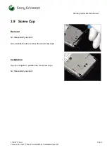
Страница 21: ... Rev 2 21 64 3 9 Screw Cap Removal No disassembly needed Use a dentist hook to remove the two Screw caps Installation Use your fingers to position the two screw caps No Reassembly needed Company Internal Sony Ericsson Mobile Communications AB ...

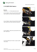
Страница 22: ...e the Cap GrommetF and QCIF VGA Camera from the Frame Sub Camera Assembly Use your fingers to remove the Cap GrommetF and QCIF VGA Camera from the Frame Sub Camera Assembly Use your fingers to remove the Cap GrommetF from the QCIF VGA Camera Use a Camera Removal Tool VGA to remove the QCIF VGA Camera Company Internal Sony Ericsson Mobile Communications AB ...

Страница 23: ...ach the QCIF VGA Camera Use your fingers to attach the Cap GrommetF to the QCIF VGA Camera Use your fingers to attach the Cap GrommetF and QCIF VGA Camera to the Frame Sub Assembly Camera Follow the 4 1 3 4 1 8 Reassembly instructions Company Internal Sony Ericsson Mobile Communications AB ...

Страница 24: ...GrommetF and QCIF VGA Camera from the Frame Sub Camera Assembly Use your fingers to detach the Cap GrommetF Installation Use your fingers to attach the Cap GrommetF Use your fingers to attach the Cap GrommetF and QCIF VGA Camera to the Frame Sub Camera Assembly Follow the 4 1 3 4 1 8 Reassembly instructions Company Internal Sony Ericsson Mobile Communications AB ...

Страница 25: ...moval Follow the 2 1 1 2 1 2 Disassembly instructions Use the Flex Film Assembly tool to remove the Keyboard Main Installation Use your fingers to position the Keyboard Main Follow the 4 1 7 4 1 8 Reassembly instructions Company Internal Sony Ericsson Mobile Communications AB ...

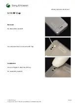
Страница 26: ... 1209 0972 Rev 2 26 64 3 13 RF Cap Removal No disassembly needed Use a Dentist Hook to remove the RF Cap Installation Use your fingers to attach the RF Cap No reassembly needed Company Internal Sony Ericsson Mobile Communications AB ...

Страница 27: ... Removal Follow the 2 1 1 2 1 3 Disassembly instructions Use a pair of tweezers to remove the On Off Key Installation Use a pair of tweezers to position the On Off Key Follow the 4 1 6 4 1 8 Reassembly instructions Company Internal Sony Ericsson Mobile Communications AB ...

Страница 28: ... 1 3 Disassembly instructions Use a Front Opening Tool to remove the SIM M2 flex module Installation Use your fingers to position the SIM M2 flex module Use your fingers to attach the SIM M2 flex module Follow the 4 1 6 4 1 8 Reassembly instructions Company Internal Sony Ericsson Mobile Communications AB ...

Страница 29: ...hanical 1209 0972 Rev 2 29 64 3 16 Memory stick 2GB M2 Follow the 2 1 1 Disassembly instructions Replace the Memory Stick 2GB M2 Follow the 4 1 8 Reassembly instructions Company Internal Sony Ericsson Mobile Communications AB ...

Страница 30: ... Removal Follow the 2 1 1 2 1 3 Disassembly instructions Use a pair of tweezers to remove the Key Volume Installation Use a pair of tweezers to position the Key Volume Follow the 4 1 6 4 1 8 Reassembly instructions Company Internal Sony Ericsson Mobile Communications AB ...

Страница 31: ... Removal Follow the 2 1 1 2 1 3 Disassembly instructions Use a pair of tweezers to remove the Key Camera Installation Use a pair of tweezers to position the Key Camera Follow the 4 1 6 4 1 8 Reassembly instructions Company Internal Sony Ericsson Mobile Communications AB ...

Страница 32: ... Removal Follow the 2 1 1 2 1 3 Disassembly instructions Use a pair of tweezers to remove the Key Music Installation Use a pair of tweezers to position the Key Music Follow the 4 1 6 4 1 8 Reassembly instructions Company Internal Sony Ericsson Mobile Communications AB ...

Страница 33: ...t air if needed Carefully remove the label without causing scratches If there still are residues clean the surface with isopropyl alcohol Check that the proper label format is loaded in the Zebra printer Write a new label by using the program Label make and check that the printing is OK Take the new label and place it onto the frame as in the adjacent picture One label only is allowed Follow the 4...

Страница 34: ...ev 2 34 64 3 21 Co Brand Label Removal No Disassembly needed Use a Dentist Hook to remove the Co Brand label Installation Use your fingers to attach the Co Brand Label No Reassembly needed Company Internal Sony Ericsson Mobile Communications AB ...

Страница 35: ...ND Removal Follow the 2 1 1 2 1 3 Disassembly instructions Use a Dentist Hook to remove the Rubber GND Installation Use a pair of tweezers to position the Rubber GND Follow the 4 1 6 4 1 8 Reassembly instructions Company Internal Sony Ericsson Mobile Communications AB ...

Страница 36: ...val Follow the 2 1 1 2 1 5 Disassembly instructions Use a Front open removal tool to remove the Shield Can Lid RF Installation Use your fingers to position a new Shield Can Lid RF Follow the 4 1 4 4 1 8 Reassembly instructions Company Internal Sony Ericsson Mobile Communications AB ...

Страница 37: ...val Follow the 2 1 1 2 1 3 Disassembly instructions Use a Front open removal tool to remove the Shield Can Lid BB Installation Use your fingers to position a new Shield Can Lid BB Follow the 4 1 6 4 1 8 Reassembly instructions Company Internal Sony Ericsson Mobile Communications AB ...

Страница 38: ...B Removal Follow the 2 1 1 2 1 3 Disassembly instructions Use a dentist hook to remove the Gasket BB Installation Use a pair of tweezers to position a new Gasket BB Follow the 4 1 6 4 1 8 Reassembly instructions Company Internal Sony Ericsson Mobile Communications AB ...

Страница 39: ...F Removal Follow the 2 1 1 2 1 5 Disassembly instructions Use a dentist hook to remove the Gasket RF Installation Use a pair of tweezers to position a new Gasket RF Follow the 4 1 4 4 1 8 Reassembly instructions Company Internal Sony Ericsson Mobile Communications AB ...

Страница 40: ... Front opening tool to remove the Shield Can Lid BB Use a pair of tweezers to remove the Sheet Isolation Installation Use a pair of tweezers to position a new Sheet Isolation and a use your fingers to position a new Shield Can Lid BB Follow the 4 1 4 4 1 8 Reassembly instructions Company Internal Sony Ericsson Mobile Communications AB ...

Страница 41: ... Removal Follow the 2 1 1 2 1 3 Disassembly instructions Use a dentist hook to remove the Sheet Lid BB Installation Use a pair of tweezers to position a new Sheet Lid BB Follow the 4 1 4 4 1 8 Reassembly instructions Company Internal Sony Ericsson Mobile Communications AB ...

Страница 42: ... Removal Follow the 2 1 1 2 1 5 Disassembly instructions Use a dentist hook to remove the Sheet Lid RF Installation Use a pair of tweezers to position a new Sheet Lid RF Follow the 4 1 4 4 1 8 Reassembly instructions Company Internal Sony Ericsson Mobile Communications AB ...

Страница 43: ...e a Front opening tool to remove the Shield Can Lid RF Use a pair of tweezers to remove the Sheet GSM Installation Use a pair of tweezers to position a new Sheet GSM and a use your fingers to position a new Shield Can Lid RF Follow the 4 1 4 4 1 8 Reassembly instructions Company Internal Sony Ericsson Mobile Communications AB ...

Страница 44: ...e a Front opening tool to remove the Shield Can Lid RF Use a pair of tweezers to remove the Sheet UMTS Installation Use a pair of tweezers to position a new Sheet UMTS and a use your fingers to position a new Shield Can Lid RF Follow the 4 1 4 4 1 8 Reassembly instructions Company Internal Sony Ericsson Mobile Communications AB ...

Страница 45: ...emoval Follow the 2 1 1 2 1 7 Disassembly instructions Use a dentist hook to remove the Spacer LCD_conn Installation Use a pair of tweezers to position a new Spacer LCD_conn Follow the 4 1 2 4 1 8 Reassembly instructions Company Internal Sony Ericsson Mobile Communications AB ...

Страница 46: ...our fingers to remove the Camera 3MPixel CMOS from the Frame Sub Camera Assembly Use your fingers to remove the Cap GrommetF from the Camera 3Mpixel CMOS Use a Camera Removal Tool 3Mpixel to remove the Camera 3Mpixel CMOS Installation Use your fingers to attach the Camera 3Mpixel CMOS Company Internal Sony Ericsson Mobile Communications AB ...

Страница 47: ...ruction Mechanical 1209 0972 Rev 2 47 64 Use your fingers to attach the Cap GrommetF to the Camera 3Mpixel CMOS Follow the 4 1 3 4 1 8 Reassembly instructions Company Internal Sony Ericsson Mobile Communications AB ...

Страница 48: ...l CMOS from the Frame Sub Camera Assembly Use your fingers to remove the Cap GrommetR from the Camera 3Mpixel CMOS Installation Use your fingers to position the Cap GrommetR on the Camera 3Mpixel CMOS Use your fingers to position the camera in the Frame Sub Camera Assembly Follow the 4 1 3 4 1 8 Reassembly instructions Company Internal Sony Ericsson Mobile Communications AB ...

Страница 49: ...the Camera 3MPixel CMOS from the Frame Sub Camera Assembly Use your fingers to remove the QCIF VGA Camera from the Frame Sub Camera Assembly Use your fingers to remove the receiver from the Frame Sub Camera Assembly Use a Flex Film Assembly Tool to remove the Camera Flex Module from the Frame Sub Camera Assembly Company Internal Sony Ericsson Mobile Communications AB ...

Страница 50: ... Assembly Use your fingers to attach the receiver to the Frame Sub Camera Assembly Use your fingers to position the QCIF Camera VGA to the Frame Sub Camera Assembly Use your fingers to position the Camera 3MPixel CMOS to the Frame Sub Camera Assembly Follow the 4 1 3 4 1 8 Reassembly instructions Company Internal Sony Ericsson Mobile Communications AB ...

Страница 51: ...al Follow the 2 1 1 2 1 5 Disassembly instructions Use a dentist hook to remove the Cushion 0 0 mm System conn Installation Use a pair of tweezers to position new Cushion 0 0 mm System conn Follow the 4 1 4 4 1 8 Reassembly instructions Company Internal Sony Ericsson Mobile Communications AB ...

Страница 52: ...ow the 2 1 1 2 1 3 Disassembly instructions Use a Front Opening Tool to remove the SIM M2 flex module Use a pair of tweezers to replace the Liquid Intrusion Indicator Installation Use your fingers to position the SIM M2 flex module 52 64 Company Internal Sony Ericsson Mobile Communications AB ...

Страница 53: ...rking Instruction Mechanical 1209 0972 Rev 2 53 64 Use your fingers to attach the SIM M2 flex module Follow the 4 1 6 4 1 8 Reassembly instructions Company Internal Sony Ericsson Mobile Communications AB ...

Страница 54: ...tructions you have to carry out in order to reassemble the phone Start DISASSEMBLY REASSEMBLY Contents page REPLACEMENTS Done 4 1 Overview The reassembly is done in the following sequence 1 Frame Sub Assembly PWB and Key Flex Assembly 2 Display 2 02A SI TFT 3 Camera Flex Module 4 Main PWB 5 Ant Main PIFA 6 Rear Cover Assembly 7 Front Cover Assembly Complete 8 Battery Battery Cover Company Internal...

Страница 55: ... Assembly PWB and Key Flex Module Take the Frame Sub Assembly PWB Use your fingers to attach the Key Flex Module Use a Flex film assembly tool to attach the camera pad Use a pair of tweezers to attach the vibrator Company Internal Sony Ericsson Mobile Communications AB ...

Страница 56: ... Instruction Mechanical 1209 0972 Rev 2 56 64 4 1 2 Display 2 02A SI TFT Use your fingers to position the display Use your fingers to snap on the display Company Internal Sony Ericsson Mobile Communications AB ...

Страница 57: ...odule Use your fingers to position the camera flex assembly Insert and tighten the two screws JCIS No 0 8Ncm Use a Flex film assembly tool to attach the music pad Use a Flex film assembly tool to attach the volume pad Company Internal Sony Ericsson Mobile Communications AB ...

Страница 58: ...Working Instruction Mechanical 1209 0972 Rev 2 58 64 Disassembly Instruction continued Use your fingers to attach the camera flex module Company Internal Sony Ericsson Mobile Communications AB ...

Страница 59: ...Main PWB Use your fingers to position the Main PWB Use your fingers to connect the three BtB connectors with the Main PWB Use your fingers to position the Main PWB Use your fingers to snap on the Main PWB Company Internal Sony Ericsson Mobile Communications AB ...

Страница 60: ...Working Instruction Mechanical 1209 0972 Rev 2 60 64 4 1 5 Ant Main PIFA Use your fingers to snap on the Antenna Main PIFA Company Internal Sony Ericsson Mobile Communications AB ...

Страница 61: ...sembly Use your fingers to attach the connector on the Rear Cover Assembly with the BtB connector on the Main PWB Use your fingers to position the Rear cover assembly Use your fingers to attach the Rear cover assembly Company Internal Sony Ericsson Mobile Communications AB ...

Страница 62: ...mplete Use your finger to position the Front Cover Assembly Complete Use your fingers to snap on the Front Cover Assembly Complete Insert and tighten the four screws Torx T6 18Ncm Use your fingers to position the two screw caps Company Internal Sony Ericsson Mobile Communications AB ...

Страница 63: ...1209 0972 Rev 2 63 64 4 1 8 Battery Battery Cover Use your fingers to attach the battery Put on the battery cover Use your fingers to lock the two locks on the side of the phone Company Internal Sony Ericsson Mobile Communications AB ...

Страница 64: ...uction Mechanical 1209 0972 Rev 2 64 64 5 Revision history Rev Date Changes Comments 1 2008 02 20 Initial release 2 2008 03 27 Changes in Chapter 3 22 and 3 28 Company Internal Sony Ericsson Mobile Communications AB ...

Отзывы: