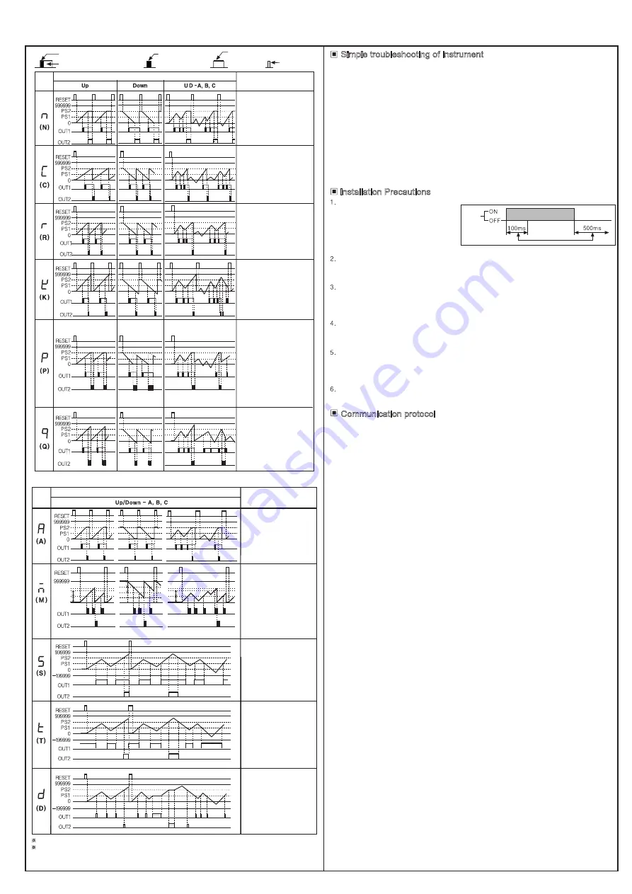
One-shot Output (0.01-99.99s)
HOLD Output
One-shot Output
HOLD Output
Output at the
same time
The OUT output of the 1-segment countermeter is the same as the OUT2 output of the 2-segment counter meter
The preset value of OUT1, OUT2 cannot be set to 0 In all output modes.
1. For the communication protocol, please refer to the General MODBUS-RTU
Communication Protocol for Counting, Timing and Frequency Products, which
can be obtained by contacting the sales.
Simple troubleshooting of instrument
1. The meter does not count or the counting is wrong
-Check whether the connecting wire of the instrument is correct.
-Check whether the input signal, level and frequency of the sensor are correct,
and whether the output indicator of the sensor flashes with the working condition.
-Check whether the input mode (IN) and counting speed (CPS) of the instrument
meet the application requirements.
-Check whether the ratio (coefficient) SCL is correct.
2. The set value cannot be modified or the panel reset key does not respond
-Check whether the LOCK key protection menu has selected the key protection
function.
3. The instrument displays "Error"
-The scale factor SCL must be less than or equal to the set value of PS1 and PS2.
Otherwise, the "Error" prompt will be displayed.
4. The count value cannot be reset to 0
-Check whether the initial value W is not equal to 0.
Communication protocol
Installation Precautions
When the power supply is ON/OFF:
The initial 100ms after power on is the
power supply rising period, and 500ms
after power off is the power supply falling
period, which is an unstable period.
Therefore, input signals after 100ms
of power on, and power on again
after 500ms of power off.
Input signal cable
①
The distance from the detection sensor to our product should be as short as possible.
②
If you need a long input signal cable, please use a shielded cable.
③
Input signal cable, power cable and power cable shall be wired separately
Contact input
If the contact is used in the counter high speed mode (1k, 5k, 10k, 20kcps), when there is
counting input, the contact will vibrate when opening and closing, resulting in abnormal input
signals and inaccurate counting. Therefore, the contact should be used in the low speed mode
(1cps or 30cps).
When installing the product on the control panel and conducting the withstand voltage and
insulation impedance test:
①
Completely separate the circuit of this product from the control panel.
②
Short circuit all terminals of the product.
Avoid using in the following places
:
①
Places with strong vibration or impact
②
Places where strong acid and alkali substances are used
③
Places with direct sunlight
④
Near the machine where strong magnetic field and electronic interference occur
Installation environment
①
Indoor
②
Pollution Degree 2
③
Below 2000m above sea level
④
Installation Category
Ⅱ
Power
Unstable
action period
Output
Mode
Input Mode
Description
After count-up, counting
display value and retained
output are maintained
until reset signal is
applied.
When count-up, counting
display value will be reset
and count simultaneously.
OUT1 retained output will be
off after OUT2 one-shot time.
The one-shot output time of
OUT1 one-shot output time
is operated regardless of
OUT2 output.
After count-up, counting
display value is reset after
one-shot output time of OUT2
and it counts simultaneously.
OUT1 retained output will be
off after
OUT2 one-shot time.
OUT1 one-shot output time is
operated regardless of OUT2
output.
After count up, counting
display value increases or
decreases untill RESET
input is applied.
OUT1 retained output is off
after OUT2 one-shot time.
OUT1 one-shot output time
is operated regardless of
OUT2 output.
After count-up, counting
display valueis maintained
while OUT2 output is on,
Counting value is internally
reset and counts simultaneously.
When OUT2 output is off,
displays counting value while
OUT2 is ON, and it increases
or decreases.
OUT1 retained output is off
after OUT2 one-shot time.
OUT1 one-short output time is
operated regardless of OUT2
output.
After count up, counting
display value increases or
decreases during OUT2
one-shot time.
OUT1 retained output is off
after OUT2 one-shot time.
OUT1 one-shot output time
is operated regardless of
OUT2 output.
M
PS2
PS1
PS2
PS1
PS1
PS1
0
PS1
PS1
Output
Mode
Input Mode
Description
After count up, counting
display value and OUT1
retained output are
maintained until RESET
input is applied.
OUT1 one-shot output time
is operated regardless of
OUT2 output.
OUT1 and OUT2 keep on
Status in following condition:
Counting display
value ≥ PRESET1
Counting display
value ≥ PRESET2
OUT1 output is off: Counting
display ≥ PRESET1
(when PRESET1 is 0, OUT1
output maintains ON state)
OUT2 keeps ON status in
following condition:
Counting display
value≥ PRESET2
When counting display value
is equal to setting value
(PRESET1, PRESET2) only,
OUT1 and OUT2 output
keeps ON status.
When setting 1kcps for
counting speed, solid state
relay output should be used.
When display value=integral
multiple of PS1,OUT1 output
reset automatically after
delay time .
When display value=PS2,
OUT1 output reset
automatically after delay time,
displayed value will return
immediately to Initial state,
output reset after setting time.
9
10
1


