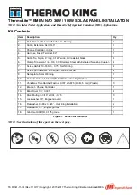
as show in Dimensions (back view of the
module) and Figure 1 (mounting detail).
The module should be fastened with four (4)
stainless steel M8 (5/16”) bolts, stainless steel
M8 washers, stainless steel M8 spring washers
and M8 (6/16”) nuts. As shown in Figure 1
(mounting detail). The stainless steel hardware
used for securing the module frame should
secure with an applied torque of 6
foot-pounds (8 Newton-meters).
The modules have been evaluated by UL for
mounting using the 4 provided mounting holes
in the frame using bolts
Figure 1
Electrical Installation
Modules should be mounted to maximize
direct exposure to sunlight and to eliminate or
minimize shadowing. Even partial shadowing
can substantially reduce module and system
output. Furthermore, partial shadowing can
elevate
the
shaded
portion’s
internal
temperature, which may lower output and
shorten module life. Bypass diodes are factory
installed. Blocking diodes should be installed in
series with each module or series string to
prevent possible back flow of energy through
the module(s) when modules or strings are
connected in parallel or used in conjunction
with a battery. If the modules are installed in
parallel electrically, each module (or series
string of module so connected) shall be
provided with the maximum series fuse as
specified.
Under
normal
conditions,
a
photovoltaic
module
may
experience
conditions that produce more current and/or
voltage than reported at Standard Test
Conditions. Accordingly, the values of short
circuit current, Isc, and open circuit voltage,
Voc, marked on modules should be
multiplied by a factor of 1.25 when
determining component voltage ratings,
conductor capacities, fuse sizes, and size of
controls connected to the module output.
Rated electrical characteristics are within
10 percent of measured values at Standard
Test Conditions of: 1000 W/m2, 25°C cell
temperature and irradiation of AM 1.5
spectrum.
A separate return wire or wires may be
required to run the positive and negative
terminations of the series string of modules to
the load. Male and/or female connectors
pre-attached to wires may be used at the
string terminations for return wire connections
and/or for source circuit box terminations. All
Details for wiring in accordance with the NEC,
and that the grounding method of the frame of
arrays shall comply with the NEC, article 250.
Grounding Specification
It is Ø4 grounding hole, in the middle of
the border of the parts back. Grounding tag
central line and grounding hole line are in
coincidence on the length direction. The tag
affixed to the frame 5mm far from the
grounding hole where is closer to the junction
box.
All module frames should be grounded for


