background image

6 Install electric heating element

7.4.3.1 Bottom connection set

Connection with the heat pump pipe inserted from
the bottom

Art.No. 25104: for heat pump pipe external dia-
meter 32, connection with 1 inch union nut

Art.No. 25105: for heat pump pipe external dia-
meter 40, connection with 5/4 inch union nut

Vent valve

1

Abb. 2-28

Abb. 2-29: Components of bottom connection set

Installation example:

vamp

air

with electric heating ele-

ment and bottom connection set

Abb. 2-30

7.4.3.2 Bottom connection set, direct connection,

3 m long

Art. 25106

Flexible connection set for connecting the heat
pump to the flow and return of the building instal-
lation.

The cable is laid in the underground waste pipe
(KG), not included in the scope of delivery.

i

Connecting cable and cable conduit must be
sealed so they are diffusion-resistant and ther-
mally-insulating

> 29

1

24

Installation manual

vampair

Содержание Vampair

Страница 1: ...Installation manual for qualified personnel Read carefully before operating DR 0072 EN v41 202205 Air source heat pump vampair ...

Страница 2: ... lines 22 7 3 Install the primary circuit circulation pump 22 7 4 Connect the primary circuit 23 7 4 1 Connection on the condenser 23 7 4 2 Cut insulating mat only required for K 08 and K 10 23 7 4 3 Primary circuit connection set 23 7 4 4 Fit temperature sensor T1 for condenser 26 7 4 5 Heat pump pipe 26 7 5 Pipe dimensions Residual delivery height information 27 7 5 1 vampair K 08 K 10 27 7 5 2 ...

Страница 3: ...002 10 office solarfocus com www solarfocus com Service Hotline Email service solarfocus at 2 Safety information Installation and commissioning Heat pump may only be installed and put into operation by certified qualified personnel SOLARFOCUS service technician or SOLARFOCUS service partner Install heat pump outdoors only Never disconnect the heat pump from the power supply except electrical work ...

Страница 4: ...yer In fulfilling the warranty guarantee services we shall cover only the assembly time and the mate rials used but not any travel or accommodation costs necessary for the fitters engineers or any return transport costs SOLARFOCUS GmbH assumes no liability for any consequential costs of damages The repair and or warranty replacement shall be carried out on site or in the SOLARFOCUS fac tory at our...

Страница 5: ... tank water precipitates out of the air Condensation forms on the cooled system parts The system must have insulation suitable for coo ling diffusion resistant Take particular care when using carbon steel risk of external corrosion Use room control with humidity sensor e g SOLARFOCUS Art 26610 This regulates the cooling flow temperature taking the room tem perature and room humidity into account a...

Страница 6: ... even over a longer period This quantity of fluid must be reliably discharged 2 methods of discharging Drain into the ground If sufficient water permeable earth layers are present it is sufficient to lay the drain pipe in gravel fill to a depth of 90 cm frost free 38 ff CAUTION When placing the heat pump close to the building it must be ensured that the condensation does not damage the buil ding C...

Страница 7: ...dH then the fill up water must be treated 3 7 2 Avoiding water side corrosion Corrosion is usually triggered by the available oxygen in the water This value can be brought into a safe range with proper planning design installation and maintenance of the heating system A constant input of oxygen should be avoided Important in this regard Expansion tank 8 Air must be prevented from being drawn in wh...

Страница 8: ...imension the expansion tank with a capacity of 12 of the total hydraulic system volume Secure the expansion tank against shut off To do this either use the shut off options on the way to the expansion tank as cap valves or unscrew the hand lever handwheel and attach it to the expan sion tank with the wire in a clearly visible position Installation of an expansion tank or a pressure maintenance sys...

Страница 9: ...since around the mid 1980s are diffusion resistant in line with DIN 4726 4 Product information 4 1 Product description The air source heat pump vampair is a compact air source heat pump for outdoor installation As stan dard it has a cooling function which extracts heat from the heating surfaces in the living area under floor heating wall heating and cools it by reversing the circulation vampair wo...

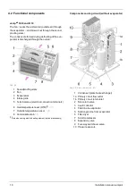
Страница 10: ... connection terminals 30 6 Overtemperature reset OTR 1 19 7 Outside temperature sensor 36 8 Condensate drain 6 1 Only when using electric heating element optional accessory Components cooling circuit without evaporator Abb 2 5 View from behind left 1 Condenser plate heat exchanger 1a Primary circuit flow outlet 1b Primary circuit return inlet 2 Non return valve 3 Liquid collector 4 Fluid line to e...

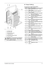
Страница 11: ... 180 4 1 9390 Connection set Optibal pump ball valve KWP10 5 1 54920 Plastic spiral hose 22 x 3 5 mm f KWP 6 1 61532 ISO Insulation for 61532 Wilo Yonos Para 25 7 5 iPWM 7 1 69034 1000 Power supply 230V AC 24V DC primary 8 1 69035 1000 Housing for display surface mounted 9 3 69095 1000 Tank sensor PT1000 PVC 5 m 10 2 69645 Immersion sleeve 1 2 x50 7 mm 11 1 69824 Sticker set ecomanager 12 1 7936 P...

Страница 12: ...for removal dismantle cladding see Prepare heat pump 17 Not included in the scope of delivery Heat pump pipe 26 electric heating element 13 lifting aid 13 pri mary circuit connection set 23 4 4 Principle of operation The function of a heat pump is similar to that of a ref rigerator from a technical standpoint but reversed The refrigerator extracts heat from the food to be coo led and releases it t...

Страница 13: ...creases efficiency while the power requirement is reduced at the same time Thus higher flow temperatures and higher heating output especially at low outside tempe ratures are possible The compression temperature decreases increasing the life expectancy of the compressor 4 6 Dimensions 4 7 Accessories Electric heating element Optional accessories Art 25200 Depending on the type of connection the el...

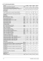
Страница 14: ...10 W35 kW 0 86 1 13 1 2 2 1 Power consumption at A7 W35 EN 14511 kW 0 88 1 24 1 2 2 4 Power consumption at A2 W35 kW 0 95 1 25 1 7 2 1 Power consumption at A 7 W35 kW 1 8 1 66 3 15 3 29 Power consumption at A7 W55 kW 1 4 1 92 1 8 3 41 Coefficients of Performance Coefficient of Performance COP at A10 W35 5 3 5 4 5 4 5 5 Coefficient of Performance COP at A7 W35 EN 14511 4 83 4 97 5 0 5 0 Coefficient...

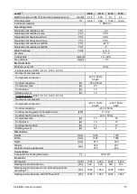
Страница 15: ...on 230 V 50 Hz 5 5 kW Control connection A 230 V 50 Hz Compressor fuse A 25 Control fuse A 10 Starting current A 15 3 phase version K 08 3 K 10 3 K 12 3 K 15 3 Number of compressors 1 Compressor connection 400 V 50 Hz 5 5 kW 400 V 50 Hz 8 kW Control connection 230 V 50 Hz Auxiliary heating power consumption max kW 3 6 9 Auxiliary heating connection 400 V 50 Hz Compressor fuse A 13 16 Control fuse ...

Страница 16: ...g into account 5 share of peak load heat generator without domestic hot water 2 With extension set low temperature cooling 3 If this volume flow is not achieved via the heat pump plate heat exchanger heating volume flow commissioning is not possible 1 About this manual 16 Installation manual vampair ...

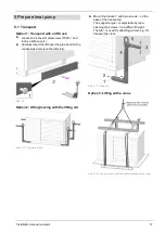
Страница 17: ...Abb 2 9 Option 2 Lifting moving with the lifting aid Abb 2 10 Lifting aid 4 part Mount the bracket 1 with two screws 2 on the base of the heat pump The support angle 3 is adjustable by repo sitioning the screws 4 to a different height The tab 5 is used for attaching a hoist e g for transport by crane Abb 2 11 Lifting aid Option 3 Lifting with a crane Abb 2 12 Crane transport with Euro pallet condi...

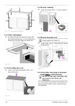
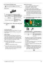
Страница 18: ...covers Abb 2 15 5 4 Remove cladding Loosen the 6 bolts TX25 1 remove cladding 2 Abb 2 16 5 5 Remove transport lock i Only required for K 12 and K 15 Loosen 4 pcs screws 1 and permanently remove transport lock 2 Abb 2 17 5 6 Connect the heat pump to the power supply before commissioning i Connect the heat pump to the power sup ply at least 12 hours before com missioning The oil sump heating then st...

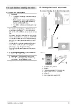
Страница 19: ...sensor of the overtemperature reset must be positioned in the heating element on site 21 The overtemperature reset protects the heating element from overheating by interrupting the power supply e g during dry running A mounting bracket is enclosed with the heating element 1 The heating element is only available for the three phase ver sion of the vampair i e K 08 3 K 10 3 CAUTION Protect the elect...

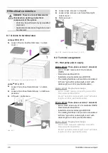
Страница 20: ...5 Vent valve 6 3 Mount heating element Mount the bracket and the heating element to the heat pump as shown Abb 2 20 6 4 Connect the heating element Connect the wires of the heating element to the contactor X2 according to the desired power Power 3 kW Connect wires A1 A2 and A3 to L1 L2 and L3 Power 6 kW Connect wires B1 B2 and B3 to L1 L2 and L3 20 Installation manual vampair ...

Страница 21: ...sert the capillary tube sensor 1 of the overtemperature reset on the bottom of the heating element into the tube about 20 cm Secure the capillary tube to one of the cables with cable ties Abb 2 21 Position temperature sensor T1 in the hea ting element Insert the temperature sensor 1 for the con denser on the top of the heating element in the intended opening Abb 2 22 Positioned sensor Abb 2 23 Ins...

Страница 22: ...pan into the drain pipe that is to be laid on site 2 Seal the empty space between drain hose and drain pipe e g with adhesive tape used to pre vent rising damp Abb 2 25 7 2 Rinse the lines Thoroughly rinse the primary circuit to remove impurities e g chips deposits CAUTION The heat pump must not yet be connected at this point Impurities must not enter the heat pump 7 3 Install the primary circuit ...

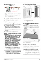
Страница 23: ...ure Avoid hose lengths smaller than 30 cm If these specifications are not adhered to there is a risk that vibrations and thus noise will be transmitted in the living space CAUTION Due to the oscillating bearing of the heat pump unit the hydraulic connection to the heating system must not be carried out as a rigid connection CAUTION The connection to the heating sys tem must not be carried out with...

Страница 24: ...mponents of bottom connection set Installation example vampair with electric heating ele ment and bottom connection set Abb 2 30 7 4 3 2 Bottom connection set direct connection 3 m long Art 25106 Flexible connection set for connecting the heat pump to the flow and return of the building instal lation The cable is laid in the underground waste pipe KG not included in the scope of delivery i Connect...

Страница 25: ... from the rear Art no 25107 Vent valve 1 Abb 2 32 Abb 2 33 Components of rear connection set Seal insulation Stick fabric tape on insulation parts at the col lision point 7 4 3 4 Rear connection set 3 m long extension Art 25108 Used to extend the rear connection set Art 25107 For connecting the rear connection set with the flow and return of the building installation i Protect the cables on site a...

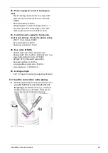
Страница 26: ...ection from the underside of the heat pump we recommend laying in the ground with the SOLARFOCUS heat pump pipe 2 dimensions available Dimensions and design external diameter 32 The dimensions are important for placement in the concrete foundation Abb 2 50 40 i Connect both pipes for bus cable and power cable once the electrical installation is com plete 29 Dimensions and design external diameter ...

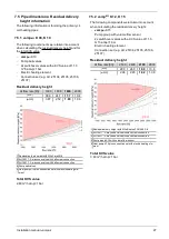
Страница 27: ...ne valve with half screw connection 4 Pump ball valves 5 Heat pump K10 plus connection set with electric heating ele ment Total KVS value 2 89 m h at p 1 bar 7 5 2 vampair K 12 K 15 The following components were taken into account when calculating the residual delivery height vampair K15 Pump group with volume flow sensor 2x switchover valves with a KVS value of 11 3 m h at Δp 1 bar Electric heati...

Страница 28: ... 10 3 Three phase version standard 400 V 5 5 kW rated current 8 A terminals 3 N PE Recommended fuse B13 A Install all current sensitive type B RCCB The rotating field does not need to be considered 2 5 mm up to 20 m cable length 4 mm with cable length over 20 m use flexible cable K 08 1 K 10 1 Single phase design 230 V 5 5 kW maximum operating current 20 A Recommended fuse B25 A 4 mm up to 20 m ca...

Страница 29: ...able cross section 1 5 mm X5 Bus cable RS485 Cable length up to 100 m 2x2x0 22 mm Cable length 100 m to 200 m 2X2x0 34 mm e g Lapp Unitronic Bus Can No 2170263 AWG22 STP Shielded Twisted Pair Nominal resistance 120 Ohm Line capacitance per metre 60 pF m Loop resistance 160 Ohm km X6 Analogue input 0 to 10 V input for heat pump output specification 8 3 Seal the connection cable piping Seal the gap ...

Страница 30: ...Abb 2 40 Terminal area K 08 K 10 Terminal area K 12 K 15 Abb 2 41 Terminal area K 12 K 15 1 Overtemperature reset OTR only used in combination with electric heating element 2 Contactor only used in combination with electric heating element 3 RCC outdoor board 4 Connection for potential equalisation 8 Electrical connection 30 Installation manual vampair ...

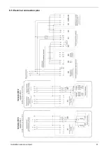
Страница 31: ...8 Electrical connection Installation manual vampair 31 8 5 Electrical connection plan ...

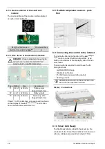
Страница 32: ... on electrical flush mounted socket is possible with boreholes 2 screw materials for installation of housing not inclu ded in scope of delivery Install the power supply in the housing 8 6 3 Display power supply Run the power supply for the display from the power supply unit supplied Display X1 Power supply unit 24 V DC Pin 1 or 2 GND Pin 3 or 4 8 6 4 Connect CAN bus Make bus cable connection from ...

Страница 33: ...k i3 Flow sensor i4 Return sensor For vampair K 08 K 10 i4 Return sensor measurement of the return temperature by means of flow sen sor Huba Control For vampair K 12 K 15 i5 Digital input for Smart Grid 1 i9 Digital input for Smart Grid 1 i15 Flow sensor made by Huba Control measurement of the flow rate For vampair K 12 K 15 o1 Primary circuit circulation pump power supply OUT1 Primary circuit cir...

Страница 34: ...for the CAN bus CAN IN and CAN OUT are located on the electronic module The terminating resistor is pre installed to CAN OUT at the factory If only one electronic module is connected to the heat pump the terminating resistor for this must be left on the CAN OUT plug If several modules are connected then the terminating resistor may only be installed on the last module in the chain the terminating ...

Страница 35: ...Screen Heating circuit Screen System parameters To ensure visibility of the parameter registration with qualified personnel code is required Electrical connection Input i1 on electronic module D1 D1i1 Contact closed heating circuit On Contact open heating circuit Off Switching contact must be potential free i When using the optional item 26100 exten sion of buffer operation with a mixed heating ci...

Страница 36: ... control Elec tronic module communication error 8 8 Outside temperature sensor posi tion Abb 2 44 8 9 Connecting the control to the internet To enable the Internet connection of the ecomanager touch control connect the Ethernet port X2 1 type RJ45 on the bottom of the display by cable to a net work router The connection is required in order to use the fol lowing functions mySOLARFOCUS app Weatherm...

Страница 37: ...rm DR 0104 for com missioning request at the end of this manual Requirements for commissioning þ The hydraulic installation of the heating system is complete þ The primary circuit was thoroughly rinsed fil led and vented þ The electrical installation of the heating system is complete Conditions for commissioning Volume flow of the heat pump for the defrosting The required volume flow for defrostin...

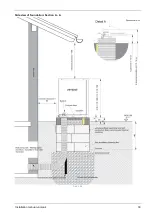
Страница 38: ...eation 10 1 Downward line connection Top view Abb 2 47 1 Condensate drain Ø 50 mm 2 Pipe for heating return connection HP 5 4 OT flat sealing 3 Pipe for heating flow connection HP 5 4 OT flat sealing 4 Conduit for bus cable Ø 25 mm 5 Conduit for electric cables Ø 50 mm 6 Installation surface concrete base insulation pay attention to horizontal and planar execution 10 Foundation plan 38 Installatio...

Страница 39: ...10 Foundation plan Installation manual vampair 39 Side view of foundation Section A A Abb 2 48 ...

Страница 40: ...Side view of foundation Section B B Abb 2 49 Detail B illustration shows the heat pump pipe external diameter 40 Abb 2 50 10 Foundation plan 40 Installation manual vampair ...

Страница 41: ...10 Foundation plan Installation manual vampair 41 10 2 Line connection to the rear Abb 2 51 10 3 Condensate drain Abb 2 52 ...

Страница 42: ...ing return Ø 35 mm plus 19 mm insulation 3 Condensate drain Ø 50 mm 4 Conduit for bus cable Ø 25 mm 5 Conduit for electric cables Ø 50 mm 6 Installation surface for insulating brick with concrete filling Note The concrete surface must be horizontal and have a flat finish 11 Flat roof set up 42 Installation manual vampair ...

Страница 43: ...11 Flat roof set up Installation manual vampair 43 Detail A illustration shows the heat pump pipe external diameter 40 Side view of foundation Section A A Abb 2 54 ...

Страница 44: ...Front view of foundation Section B B Abb 2 55 11 Flat roof set up 44 Installation manual vampair ...

Страница 45: ...s max 1 unmixed heating circuit Observe min 22 m heatable floor area without single room control and minimum volume flow of 1560 l h for K08 and K10 and 2500 l h for K12 and K15 in case of defrosting via heating circuit Observe residual delivery height of primary circuit circulation pump Note the overflow valve setting Suitable for room cooling ...

Страница 46: ...table floor area without single room control and minimum volume flow of 1560 l h for K08 and K10 and 2500 l h for K12 and K15 in case of defrosting via heating circuit Observe residual delivery height of primary circuit circulation pump Note the overflow valve setting Suitable for room cooling 12 Plant schematic 46 Installation manual vampair ...

Страница 47: ...ating circuit DHW tank and buffer tank Suitable for new builds max 1 unmixed heating circuit Observe minimum volume flow of 1560 l h for K08 and K10 and 2500 l h for K12 and K15 in case of defrosting via heating circuit Note the overflow valve setting Suitable for room cooling ...

Страница 48: ... and K15 in case of defrosting via heating circuit Note the overflow valve setting vampair for a mixed unmixed heating circuit with DHW tank and buffer tank Suitable for new builds and renovated buildings up to 8 mixed heating circuits possible Decoupling of primary circuit and heating circuit Easy to integrate additional heat generators 12 Plant schematic 48 Installation manual vampair ...

Страница 49: ...ircuits possible Decoupling of primary circuit and heating circuit vampair for a mixed unmixed heating circuit with stratified buffer tank and fresh water module Suitable for new builds and renovated buildings up to 8 mixed heating circuits possible Hygienic hot water preparation with FWM Decoupling of primary circuit and heating circuit Easy to integrate additional heat generators ...

Страница 50: ...table for new builds and renovated buildings up to 8 mixed heating circuits possible Hygienic domestic hot water preparation with fresh water module plus circulation Decoupling of primary circuit and heating circuit Easy to integrate additional heat generators 12 Plant schematic 50 Installation manual vampair ...

Страница 51: ...12 Plant schematic Installation manual vampair 51 ...

Страница 52: ... þ_Heat pumps þ_Fresh water technology Everything from a single source Pellets Log wood Wood chips Heat pump Innovative products that are easy on the environment and your wallet Log wood pellets Solar energy Fresh water makes you independent ...

Отзывы: