December 2020
|
Solar Stik
®
, Inc.
32
|
SYSTEM SETUP AND OPERATION GUIDE FOR THE SOLAR STIK USAF G-BOSS MEDIUM AND HEAVY HYBRID POWER SYSTEM
PRELIMINARY DRAFT
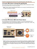
Use 5’ Inter-Connect cables (E) to connect the System batteries to PRO-Verter as shown in Figure
18. Connect the PRO-Verter to the Inter-Connect Strip
Note:
A variety of Energy Storage Modules (ESMs) may be connected to the PRO-Verter. Never
mix battery chemistries in a System.
a Connect PRO-Verter to Energy Storage Modules
Figure 18. PRO-Verter to ESM connections
24VDC PRO-Verter 5000
Li ESM 2000 (x6)
Inter-Connect Strip 7s
PRO-Verter 5000
left-side view
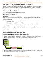
Use the Generator AC Power Cable (Heavy, 50’; Medium, 10’) to connect the generator to the
“120VAC/50A INPUT” port on the left side of the PRO-Verter 5000. A custom cable or adaptor may
be required to connect grid power to the PRO-Verter 5000.
b Connect PRO-Verter 5000 to AC Power Source
120 VAC / 15 A
60 Hz
grid power
OR
120 VAC / 50 A
60 Hz
fuel-powered
generator 3-5 kW
Note:
The TQGs must be equipped with a Solar Stik Remote-start Enabling Kit (RsEK) installed to
be compatible with the PRO-Verters 5000. The PRO-Verter 5000 must be equipped with a Solar
Stik RMK AGS to communicate with and control the AMMPS series of generators. Currently, the
PRO-Verter 5000 is not capable of interfacing with the 1–2 kW Man Portable Generators (Ranger/
Defender).
E
B
Figure 19. Connecting AC power sources to PRO-Verter


