


WATTrouter Mx - user manual
How to fit and setup the device
Page 9 from 82
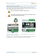
FITTING THE DEVICE
WATTrouter Mx regulator may be fitted in a regular electrical distribution box onto a 35 mm DIN rail or
attached to a wall using 2 screws with round or countersink head and with diameter up to 6 mm.
WATTrouter Mx current sensing module may be fitted in a regular electrical distribution box onto a 35 mm DIN
rail.
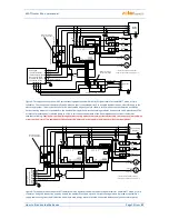
Measuring inputs of the current sensing module may be connected as single, double, or triple-phase
connections.
The recommended maximum distance of the current sensing module and the regulator is 2 meters. Bigger
distance is acceptable, but it will slightly affect the measuring accuracy.
If CYKY or other thick and hard cables cannot pass through current transformers easily, use flexible cables to
extend the existing connections. When fitting the current sensing module do not press hard on it. You may
damage the module.
Tip:
Individual phase wires may pass through the current sensing module from either direction. The direction of
currents may be configured in the control software.
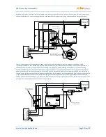
To connect power supply to the regulator (L1 and N) use wires with a minimum cross-section of 0.5 mm
2
, for
example CYKY 1.5.
To connect loads to the relay outputs use wires with adequate cross-section corresponding with the power
ratings of the connected loads.
To connect loads to the power SSRs again use wires with adequate cross-section corresponding with the power
ratings of the connected loads.
To interconnect the current sensing module and regulator (inputs Y and ILx) use 4-wire cable with cross-section
from 0.5 to 1.5 mm
2
. If these wires are longer than 2m or are placed in a cable tray together with other power
cables/wires, we recommend using a shielded cable. Similar recommendation applies for connecting external
current transformers to the ANDI inputs.
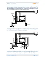
To interconnect power SSR control inputs and/or 0-10VDC control signals with SSR outputs use wires with
cross-section from 0.5 to 1.5 mm
2
. If these wires are longer than 2m or are placed in a cable tray together with
other power cables/wires, we recommend using a shielded cable.
To interconnect S0 impulse signals from external energy meters with ANDI inputs use 2-wire cable with cross-
section from 0.5 to 1.5 mm
2
, connected between GND and respective ANDI terminal. If these wires are longer
than 2m or are placed in a cable tray together with other power cables/wires, we recommend using a shielded
cable.
To interconnect analog temperature sensors with ANDI inputs use 2-wire shielded cable with cross-section
from 0.5 to 1 mm
2
, connected between GND and respective ANDI terminal.
To interconnect digital temperature sensors of type DS18x20 to DQ bus use 3-wire shielded cable with cross-
section from 0.5 to 1 mm
2
, connected between GND (ground), +5V (power supply) and DQ terminal (data bus).
When connecting other sensors to the DQ data bus always connect shielding. Total length of the bus including
all branches should not exceed 50m.
Connect shielding of all shielded cables to the GND terminal as close as possible to the regulator.
If you use shielded cables then use for each type of signal a standalone shielded cable, i.e. do not mix signals
from analog and digital sensors in one cable, especially when making the cables longer. There might be
crosstalk which will decrease measurement accuracy.


