Page 21 / 28
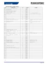
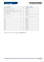
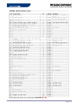
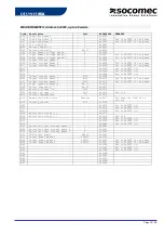
STANDARD JBUS/MODBUS TABLES IN PARALLEL SYSTEM CONFIGURATION
Reminder
In UPS parallel system configuration, there is only one
J
J
B
B
U
U
S
S
/
/
M
M
O
O
D
D
B
B
U
U
S
S interface. The addresses mapping
gives the possibility to read data from each module and common bypass. There is no link between the
J
J
B
B
U
U
S
S
/
/
M
M
O
O
D
D
B
B
U
U
S
S
salve number and the UPS unit or module one.
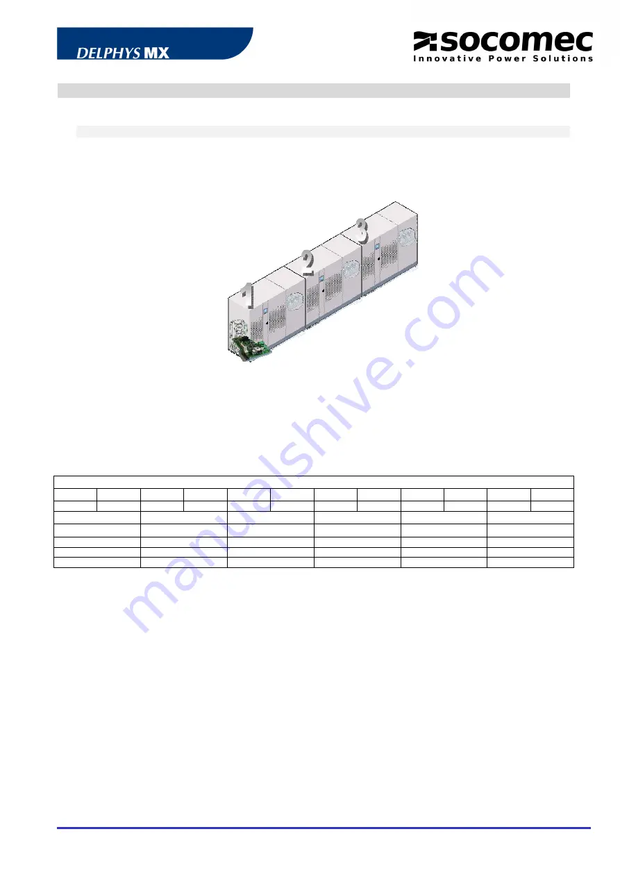
The interface is plugged in the ‘com-slots’ of the common cabinet is case of central bypass installation or in
the UPS unit 1 “com slots” in case of modular system (see bellow).
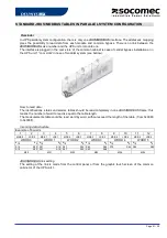
How to read data:
The identifications, status and alarms tables should be read completely in one JBUS/MODBUS frame; this
means the number of word to read is equal to the table length.
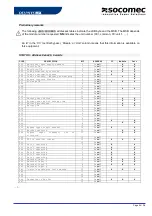
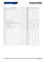
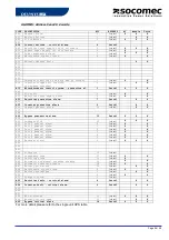
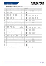
The measurements table could be read word by word, without exceed the length of the table. (from 0x0060
to 0x008F).
Incoming data structure:
Example of 6 words
1
2
3
4
5
6
7
8
9
10
11
12
MSB 0
LSB 0
MSB 1
LSB 1
MSB 2
LSB 2
MSB 3
LSB 3
MSB 4
LSB 4
MSB 5
LSB 5
WORD 0
WORD 1
WORD 2
WORD 3
WORD 4
WORD 5
b15
b0 b15
b0 b15
b0 b15
b0 b15
b0 b15
b0
S15
S00 S31
S16 S47
S32 S63
S48 S79
S64 S95
S80
A15
A00 A31
A16 A47
A32 A63
A48
M00
M01
M02
M03
M04
M05
J
J
B
B
U
U
S
S
/
/
M
M
O
O
D
D
B
B
U
U
S
S link setting
The setting of the link is made from the control panel or from the graphic touch screen of the common
cabinet or of the UPS unit 1.


