Snapper SGV13321KW Скачать руководство пользователя страница 9


11

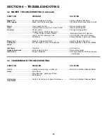
SECTION 3 – OPERATING INSTRUCTIONS


WARNING 

DO NOT allow operation of the machine by 
untrained personnel. 

 
IMPORTANT!  BEFORE OPERATING:


Be thoroughly familiar with all controls and how to use 
them before operating the machine. Know beforehand 
how to 

STOP

 machine motion, mower blades and 

engine in preparation for possible emergencies. 
 

3.1  CONTROLS & THEIR FUNCTIONS


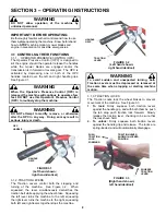
3.1.1.  OPERATOR PRESENCE CONTROL (OPC) 
The Operator Presence Control (OPC) is designed to 
kill the engine should the operator release the handles 
while the mower blades are engaged and/or the 
transmission is in forward or reverse gear.  The OPC is 
activated by depressing one or both of the OPC 
handles located over the left and right handle grips.  
See Figure 3.1.   
 

WARNING 

When the Operator’s Presence Control (OPC) is 
released, the machine will continue to operate a few 
feet. DO NOT use this Operator’s Presence Control 
(OPC) to routinely stop the machine. 


WARNING 

DO NOT attempt to modify, remove, or otherwise 
alter the OPC in any way.  Doing so may result in 
serious injury or death. 


FIGURE 3.1 

(Left hand shown; 

right hand identical)


3.1.2. TRACTION LEVERS 
The Traction Levers control both the stopping and 
turning of the machine.  See Figure 3.2.  When 
squeezed, the lever simultaneously declutches the 
traction belt while applying the wheel brake.  Squeezing 
the left lever turns the machine to the left, squeezing 
the right lever turns the machine to the right, squeezing 
both left and right levers together stops the machine. 


FIGURE 3.2 

(Left hand shown; 

right hand identical)


WARNING 

To avoid sudden and unexpected turning, both 
Traction Levers must be depressed or released at 
the same time when stopping or starting machine 
motion. 

 
3.1.3. TRACTION LOCKS 
The Traction Locks lock the wheel brakes to prevent 
movement of the machine.  See Figure 3.3. 

1. To lock:

 Firmly squeeze both traction levers 

against the handle grip, and with both thumbs, push 
the tab atop each traction lock forward.  Slowly 
release the traction lever, checking to be sure that 
the locks have held. 

2. To unlock:

 Firmly squeeze both traction levers 

against the handle grip and release.  The locks are 
spring-loaded, and will automatically disengage. 


FIGURE 3.3 

(Right hand shown; 

left hand identical)


OPC  
HANDLE 

HANDLE 
GRIP 

HANDLE 
GRIP 

TRACTION 
LEVER 

PUSH  
TRACTION 
LOCK 
FORWARD

TRACTION LEVER 
SHOWN IN LOCKED 
POSITION 

SQUEEZE 
TRACTION 
LEVER  

9

Содержание SGV13321KW

Страница 1: ...t Before operating your PRO SERIES WALK BEHIND read this manual carefully and pay particular attention to the IMPORTANT SAFETY INSTRUCTIONS on Pages 2 4 Remember that all power equipment can be danger...

Страница 2: ...handling and the stability of the machine 4 DO NOT use tow behind attachments on slopes 5 AVOID uphill starts 6 Turf conditions can affect the machine s stability DO NOT operate machine under any cond...

Страница 3: ...blades must be OFF and Traction Levers LOCKED in the Traction Lock position OPERATION Continued From Previous Column 3 Stop Blades when crossing gravel drive walks and under any conditions where thro...

Страница 4: ...nnect positive first and negative last Charge battery in an open well ventilated area free from spark and flames Unplug charger before connecting or disconnecting from battery Wear protective clothing...

Страница 5: ...on Troubleshooting 16 SECTION 5 MAINTENANCE 17 General Maintenance Schedule 17 Safety Interlock System Checks 17 SECTION 6 ADJUSTMENTS REPAIRS 18 23 Lower Traction Rod Adjustment 18 Upper Traction Rod...

Страница 6: ...become thoroughly familiar with the controls components and operation of this machine before operating Specific details involving the engine are found in the separate engine owner s manual Study these...

Страница 7: ...R S PRESENCE CONTROL OPC RIGHT HAND TRACTION LEVER RIGHT HAND TRACTION LOCK TRANSMISSION SHIFT LEVER ENGINE SPEED CONTROL CHOKE CONTROL LEFT HAND TRACTION LEVER LEFT HAND TRACTION LOCK LEFT HAND OPERA...

Страница 8: ...D OPERATING INSTRUCTIONS SECTION 2 DECAL IDENTIFICATION DANGER ROTATING BLADES KEEP CHILDREN AND OTHERS OUT OF THE MOWING AREA DANGER ROTATING BLADES TRANSMISSION SHIFT INDICATOR CAUTION OPEN BELT DRI...

Страница 9: ...d identical 3 1 2 TRACTION LEVERS The Traction Levers control both the stopping and turning of the machine See Figure 3 2 When squeezed the lever simultaneously declutches the traction belt while appl...

Страница 10: ...s the cutting blade clutch Pulling the switch knob up to the ON position engages the blade clutch Pushing the switch knob down to the OFF position disengages the blade clutch See Figure 3 6 FIGURE 3 6...

Страница 11: ...ushing the Mower outside where fumes can be dissipated Make sure Fuel Tank Cap is tightened after refueling Refer to Engine manual for fuel specifications NOTE DO NOT add fuel while engine is running...

Страница 12: ...n NEUTRAL position and Blade Clutch Switch is in OFF position WARNING DO NOT leave machine with engine running Stop engine Stop blades Lock traction levers Remove key DO NOT park machine on slopes 3 4...

Страница 13: ...e lever is squeezed the sharper the turn will be 3 To Stop Machine Motion squeeze both Traction Levers firmly against handle grips See Figure 3 18 NOTE The harder the levers are squeezed the harder th...

Страница 14: ...eed WARNING DO NOT operate blades in reverse Stop blades LOOK and SEE behind and down for children pets and hazards before and while backing Engine speed must be set to SLOW before operating in revers...

Страница 15: ...y Air Filter Clean or replace Filter Idles Poorly Fuel Filter plugged Replace Fuel Filter Engine Engine Oil low in Crankcase Add Oil Overheats Engine Cooling Fins clogged Clean Engine Cooling Fins Mac...

Страница 16: ...s Fill Tires with Correct Air Pressure Dull Blades Sharpen Blades or Install new Blades Mower not Broken or slipping Deck Belt Adjust or Replace Deck Belt cutting full Dull Damaged or Worn Cutting Bla...

Страница 17: ...ugs See Engine Manual Lube Controls and Linkages Use Medium Duty Oil 5 2 SAFETY INTERLOCK SYSTEM CHECK This machine is equipped with an electrical safety interlock system that is provided for the safe...

Страница 18: ...ark plug and secure it away from the plug 3 Remove pin and washer from top of rod and pull rod end out from traction lock and traction lever 4 Turn rod clockwise into fitting 1 2 turns Replace rod thr...

Страница 19: ...oving position of CUTTING BLADE on cutting blade spindle shaft 2 Moving position of CUTTING DECK 6 6 1 CUTTING BLADE ADJUSTMENT Each cutting blade assembly is equipped with six 1 4 spacers four below...

Страница 20: ...r Loosen axle bolts and adjust axle assembly up or down to correspond with front caster adjustment See Figure 6 9 NOTE When adjusting axle make sure that rear of cutting deck is 1 4 higher than front...

Страница 21: ...y remove belt from unit Be sure to reconnect harness after new belt is installed 4 Install new belt using same pulley routing See Figure 6 11 5 Slide idler pulley back against belt and adjust belt ten...

Страница 22: ...C approximately 1 4 1 2 then retighten screws Torque to 150 in lbs NOTE Make sure both OPCs are adjusted evenly FIGURE 6 15 6 11 REPLACEMENT PARTS To retain the quality of your mower use Genuine SNAPP...

Страница 23: ...tal from the heavy end of the Blade 7 Place the Blade mounting bolt through bevel washer and into Blade and place Blade Spacers over Bolt Make certain each Blade is installed with the same amount of S...

Страница 24: ...E RED TRANSMISSION YELLOW BLACK WIRING SCHEMATIC FOR PISTOL GRIP HANDLE ELECTRIC BLADE BRAKE CLUTCH TRANS SWITCH SEE NOTE RED 16 GA ENGINE YELLOW 16 GA L H OPC GREEN 14 GA FUSE IGNITION PTO SWITCH ELE...

Страница 25: ...e original purchase date SNAPPER will not be responsible for any installation cost incurred The battery warranty only covers original equipment batteries and does not cover damage to the battery or ma...

Страница 26: ..._______________________ Retailer s Phone Number_________________________________________________ It is very important that you register your purchase with Snapper to ensure warranty coverage Please ma...

Страница 27: ...27 PRIMARY MAINTENANCE...

Страница 28: ...28 PRIMARY MAINTENANCE...

Страница 29: ...29 PRIMARY MAINTENANCE...

Страница 30: ...30 PRIMARY MAINTENANCE...

Страница 31: ...31 NOTES...

Страница 32: ...t your Snapper product contact your local authorized Snapper dealer or contact Snapper Customer Service at Snapper McDonough GA 30253 Phone 1 800 935 2967 COPYRIGHT 2005 SNAPPER A Division of Simplici...

Отзывы: