Snap-on • 9
Brake Lathes
Reconditioning Disc
Brake Rotors
1.
Inspect the rotor carefully for scoring, rust ridges
(at the inner and outer circumference of the rotor), and
hard spots. Any excessive wear or deformity should
be noted and, if not within acceptable limits, the rotor
should be replaced.
2.
Use a micrometer to check the thickness of the
rotor (figure 5) at no less than 3 points around the cir-
cumference about 1" (2.54 mm) in from the outer
diameter.
If the rotor thickness varies between readings, it
should be reconditioned. However, if the thickness is
less than the minimum established by the manufac-
turer, or if it will be less after reconditioning, the rotor
should be replaced.
Note:
Most often the DISCARD thickness dimension
is cast or stamped
into the rotor, not the
minimum machine-to
thickness.
Figure 5
Set Up and Reconditioning Rotors
1.
Install a silencer band on the mounted rotor.
Stretch the band around the rotor and hook the metal
loop over a lead weight.
2.
Center the twin cutter to the rotor. Loosen the
stud nut and adjust the twin cutter so that the rotor is
centered between the tool bits. Tighten the stud nut
firmly.
3.
Install the safety shield as shown. Review the
cautions and dangers section and the general safety
information at the beginning of this manual. The safety
shield is easily screwed onto the twin cutter in the
threaded mounting hole provided.
Always wear safety glasses or a face shield.
Cutting or grinding on an exposed surface
such as a rotor will produce flying chips
and debris.
4.
Turn the rotor slide handwheel clockwise to posi-
tion the rotor slide about 1/2" away from the
rotor/silencer band (vented rotors), or 1/2" away from
the edge of the rotor (non-vented rotors).
5.
Make sure that the tool bits clear the rotor sur-
faces and the silencer band. Give the rotor a full turn
by hand and watch for clearance all the way around.
6.
Turn the lathe ON.
7.
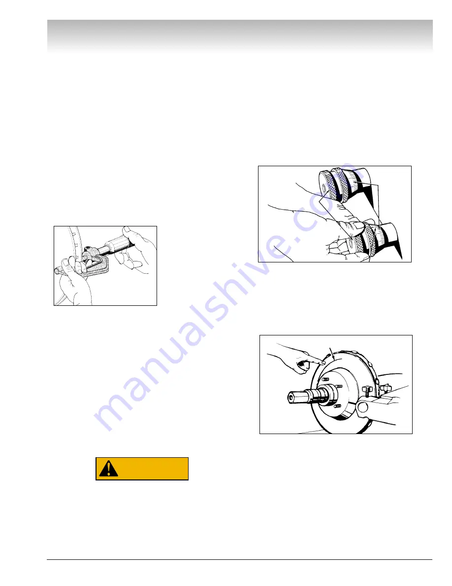
Turn each tool bit control (the outer knurled
knobs, clockwise until the tool bits just contact the
rotor surfaces.
Figure 6
8.
When the tool bits make contact, rotate each of
the inner depth-of-cut collars to zero and back the tool
bits away from the rotor.
From this point on, all tool adjustments will be made
with the tool bit controls. Then inner depth-of-cut col-
lars will be the reference and should not be moved.
Figure 7
9.
Turn the rotor slide handwheel until the tool bits
are at mid-point of the rotor face.
10.
Turn the left-hand tool bit control until the tool
bit contacts the rotor surface and makes a scratch cut.
After the cut is made, back the tool bits off and turn
the lathe OFF.
The scratch will usually appear as an incomplete cir-
cle. This is caused by runout or wobble due to rotor
condition, or by the way the rotor is mounted on the
arbor.
WARNING
Inner depth-
of-cut collars
Tool bit controls
Hold knob with one
hand – turn collar
Each increment =
0.002” english,
0.05 mm metric
First scratch cut
Micrometer


