background image

5

Service

MAINTENANCE

ENGINE OIL

With strict emission control regulations now in effect, the CF-4
and CG-4 engine oils have been developed for use with low
sulfur fuels, for On-Highway vehicle engines. When Non-Road
engines run on high sulfur fuel, it is advisable to use a "CF or
better" classification engine oil with Total Base Number (a mini-
mum TBN of 10 is recommended).

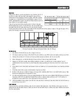
Check the engine oil before starting or more than 5 minutes
after stopping the engine. If oil level is low, remove oil filler plug
and add new oil to the prescribed level. Do not overfill. Engine
oil should be MIL-L2104C or have properties of API Classifications CD grades or higher. Change the type of  En-
gine oil according to the ambient temperature.

Starting Temperature Range Anticipated Before Next Oil Change
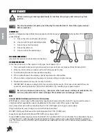
HYDRAULIC OIL

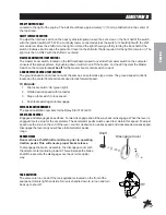
1. Use SAE 10W-40 API Service SJ or higher motor oil.

2. For proper warranty, change oil the first 50 hours and then every 500 hours or annually, which ever is first.

3. Oil level should be 2-2½" (5-6.4cm) from top of the tank when fluid is cold. Do not overfill.

4. After changing oil, run the machine for a few minutes. Check oil level and for leaks.

5. Always use extreme caution when filling hydraulic oil tank or checking level to keep system free of

contaminants.


Check and service more frequently when operating in extremely cold, hot or dusty condi-

tions.

6. If the natural color of the fluid has become black or smells burnt, it is possible that an overheating problem

exists.

7. If fluid becomes milky, water contamination may be a problem.

8. If either of the above conditions happen, change oil immediately after fluid is cool and find the cause.


Take

fluid level readings when the system is cold.

9. In extreme temperatures you can use straight weight oil. We recommend SAE 30W API Service SG when

hot (above 90°F (33°C)) and SAE 10W API Service SJ or higher when cold (below 32°F (0°C) ambient
temperature. Use either motor oil or hydraulic oil, but do not mix.

10. Oil being added to the system must be the same as what is already in the tank.


Mark the tank fill area as

to which type you put in.
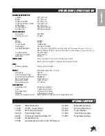
TIRE PRESSURE

Caution must be used when inflating a low tire to recommended pressure. Over inflating can cause tires to ex-
plode. Front tires should be 20 psi (1.4bar) and rear tires should be 30 psi (2.0bar). Improper inflation will reduce
tire life considerably.
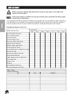
O= Recommended

X= Not Recommended

Lubricating Oil Class

CF-4

O

X

CG-4

O

X

Fuel

Содержание 30-000-C

Страница 1: ...Spray Star 3180 Model 30 000 C SN 300G236 February 2016 Product Support Hwy SS Poplar Ave Cameron WI 54822 1 800 891 9435 productsupport smithco com Parts Service ...

Страница 2: ...56 57 Plumbing 3185 3186 Envizio Pro II SharpShooter 58 59 Plumbing 3187 3188 Raven 440 SharpShooter 60 63 Controls 3182 System Raven 440 64 65 Controls 3184 System Raven 203 66 67 Controls 3185 3186 Envizio Pro II SharpShooter 68 69 Controls 3187 3188 Raven 440 SharpShooter 70 71 16 524 Motorized Control Valve 72 15 737 Strainer 72 15 743 Manifold Ball vlave 74 75 17 580 20 Heavy Duty Boom 76 79 ...

Страница 3: ...mithco Smithco machines have a Serial Number and Model Number Both numbers are needed when ordering parts Refer to engine manual for placement of engine serial number For product and accessory information help finding a dealer or to register your procuct please contact us at www Smithco com Information needed when ordering replacement parts 1 Model Number of machine 2 Serial Number of machine 3 Na...

Страница 4: ... before starting the engine 12 Never use your hands to search for oil leaks Hydraulic fluid under pressure can penetrate the skin and cause serious injury 13 This machine demands your attention To prevent loss of control or tipping of the vehicle A Use extra caution in backing up the vehicle Ensure area is clear B Do not stop or start suddenly on any slope C Reduce speed on slopes and in sharp tur...

Страница 5: ... 10 Turf 20 psi 1 4 bar Rear Two 29 x 14 00 x 15 Multi Trac 30 psi 2 0 bar SPEED Infinitely Variable 0 10 m p h 0 18 kph BATTERY Automotive type 24F 12 volt BCI Group Size 24 Cold CrankingAmps 900 minimum Ground Terminal Polarity Negative Maximum Length 10 25 26 cm Maximum Width 6 88 17 cm Maximum Height 10 25 cm FLUIDCAPACITY Crankcase Oil See Engine Manual Fuel 7 gallon 26 5 liters Hydraulic Flu...

Страница 6: ...e element every year or every 6 months 7 IMPORTANT Make sure wing bolt for the element is tight enough If it is loose dust and dirt may be sucked in wearing down the cylinder liner and piston ring resulting in poor power output Do not use petroleum solvents e g kerosene which will cause cartridge to deteriorate Do not use pressurized air to clean cartridge Pressurized air can damage cartridge FUEL...

Страница 7: ...es Check oil level and for leaks 5 Always use extreme caution when filling hydraulic oil tank or checking level to keep system free of contaminants Check and service more frequently when operating in extremely cold hot or dusty condi tions 6 If the natural color of the fluid has become black or smells burnt it is possible that an overheating problem exists 7 If fluid becomes milky water contaminat...

Страница 8: ...should be used when connecting a booster battery Use proper polarity in order to prevent sparks TOJUMPSTART NEGATIVEGROUNDEDBATTERY 1 Shield eyes 2 Connect ends of one cable to positive termi nals of each battery first A then B 3 Connect one end of other cable to negative terminal of good battery C 4 Connect other end of cable D to engine block on unit being started NOT to negative terminal of bat...

Страница 9: ...as an automotive type cruise The ground speed control is located on the center floorboard and is used to lock forward speed TOENGAGE 1 Flip rocker switch On green light 2 Obtain desired speed with foot pedal 3 Step on foot switch to lock speed 4 Push foot switch again to disengage SPEEDCALIBRATIONNUMBERS The speed calibration numbers for the Spray Star 3182 is 612 SPRAYBOSSCONTROL Engages and dise...

Страница 10: ... maintenance should be more frequent Duplicate this page for routine use Mon Tues Wed Thurs Fri Sat Sun Check the Safety Seat Switch Check Steering Operation Check the fuel level Check the engine oil level Check the condition of the air filter Clean the engine cooling fins Check for unusual engine noises Check the hydraulic oil level Check hydraulic hoses and fittings for damage Check for fluid le...

Страница 11: ...age Check radiator hoses and clamp bands Change engine oil 1 Check idle speed Replace oil filter cartridge 1 Change hydraulic oil filter 1 Check air intake line 1 Torque the wheel lug nuts 64 74 ft lb 87 100 Nm Clean Water Jacket and radiator interior Replace fan belt Every 800 hours Check valve clearance Every 1500 hours Check injection nozzle pressure Check turbo charger Check injection pump Che...

Страница 12: ...ne oil or equivalent 3 Lubricate all grease points 4 Check coolant protection and level 5 Clean exterior surface of engine 6 Seal all openings in engine and accessories with non hygroscopic material Mask off all areas to be used for electrical contact 7 Tape all openings and make sure all surfaces are dry Then spray all taped openings all engine accesso ries including ignition wiring and all exter...

Страница 13: ...11 Service NOTES ...

Страница 14: ...ht 1 15 782 Non Lighted Switch 1 9 15 729 Mount Panel Middle 1 15 726 Lighted Switch 1 15 732 Rocker Green 1 10 15 729 Mount Panel Middle 1 15 726 Lighted Switch 1 15 731 Rocker Amber 1 11 15 729 Mount Panel Middle 1 15 727 Rocker No Light 1 15 728 Centering Switch Momentary On Off On 1 12 15 725 Mount Panel End 1 15 727 Rocker No Light 1 15 728 Centering Switch Momentary On Off On 1 Color Code Ch...

Страница 15: ...107 Wire Harness Battery ground to Fuse 1 20 33 084 Magnetic Coil 1 21 48 147 Ground Battery Cable 1 22 33 216 Battery 1 23 30 106 Wire Harness Battery to Fuse 1 24 76 326 Battery Cable 1 25 30 104 Manual Hand Brake 1 26 16 883 Speed Sensor 1 27 12 003 Park Brake Toggle Switch 1 30 143 Toggle Switch Guard 1 28 31 071 Speedometer Wire 1 29 30 130 Fuel Pump 1 30 77 261 Circuit Breaker 40 amp 1 NA 30...

Страница 16: ...14 Diagrams HYDRAULICDIAGRAM Use dielectric grease on all electrical connections Letter Code Chart C Center I Inside O Outside T Top B Bottom ...

Страница 17: ... 1 12 18 405 RunTee 1 13 30 086 Hydraulic Hose 1 14 30 085 Hydraulic Hose 1 15 30 090 Hydraulic Hose 2 16 30 087 Hydraulic Hose 2 17 30 099 Wheel Drive 2 18 30 100 Hydraulic Release Brakes 2 19 30 101 Eaton Wheel Motors 2 20 30 089 Hydraulic Hose 4 21 30 103 Hot Oil Shuttle Manifold 1 22 18 395 Union Tee 1 23 30 088 Hydraulic Hose 1 24 60 215 Oil Filter Assembly 1 60 334 Replacement Element 1 25 8...

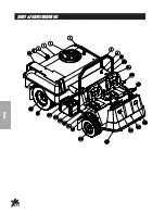
Страница 18: ...16 Parts BODY FRAMEDRAWING ...

Страница 19: ...r 1 8 31 048 T Handle Latch 1 9 31 046 Engine Cover Fiberglass 1 10 27 055 Flush Hinge 2 HSM 10 32 100 Machine Screw 10 32 100 12 HNFL 10 32 Flange Whiz Lock Nut 10 32 12 11 14 270 Seat 2 14 292 Seat Switch 1 12 76 198 03 Seat Belt 2 13 13 718 15 Steering Wheel 1 13 726 Center Cap 1 27 077 Decal Smithco Round 1 14 32 014 Headlight 2 15 31 044 Nose Cone Fiberglass 1 50 400 Grommet 1 16 30 250 Main ...

Страница 20: ...18 Parts NOSECONEDRAWING ...

Страница 21: ...ht 1 15 729 Mount Panel Middle 1 15 728 Centering Switch Momentary On Off On 1 14 LEFT BOOM 15 725 Mount Panel End 1 15 727 Rocker No Light 1 15 728 Centering Switch Momentary On Off On 1 15 10 556 Speedometer 1 16 32 014 Head Light 2 17 HSM 10 32 100 Machine Screw 10 32 x 1 8 HNFL 10 32 Flange Whiz Lock Nut 10 32 8 18 20 596 Dash Panel 1 20 545 Decal Dash Panel 1 HSM 10 32 100 Machine Screw 10 32...

Страница 22: ...20 Parts NOSECONEDRAWING ...

Страница 23: ...l 1 29 HB 14 20 075 Bolt 1 4 20 x 3 4 2 HNFL 14 20 Flange Whiz Lock Nut 1 4 20 2 30 31 049 Button Plate 1 31 33 509 Master Control Switch 2 HSTP 14 20 075 Machine Screw 1 4 20 x 3 4 4 32 7 867 SAE 6 Adapter 4 33 15 301 Orbitrol 1 34 13 488 Ignition 1 35 12 017 Hour Meter 1 36 50 359 Warning Indicator Light 3 ...

Страница 24: ...22 Parts LINKAGEDRAWING ...

Страница 25: ... 16 125 Bolt 3 8 16 x 11 4 1 HNTL 38 16 Lock Nut 3 8 16 1 9 76 296 Pedal Mount 2 18 234 Bushing 4 HG 14 28 180 Grease Zerk 2 10 31 050 Reverse Pedal 1 11 21 462 Ball Joints 6 HN 516 24 Nut 5 16 24 6 12 31 054 Pedal Rod 2 13 10 178 Relay 1 18 234 Bushing 2 HG 14 28 180 Grease Zerk 1 14 31 055 Linkage Rod 1 15 15 692 Pedal Relay 1 16 13 632 Push Pull Cable 1 17 30 159 Spray Boss Arm 1 18 30 152 Push...

Страница 26: ...24 Parts FRONTAXLEDRAWING ...

Страница 27: ...9 Hydraulic Cylinder 1 14 531 Seal Kit 1 18 171 3 8 Seal Loc Adapter 2 13 18 154 Rod End 3 HNJ 58 18 Jam Nut 5 8 18 3 HG 14 28 90 Grease Fitting 1 4 28 x 90 3 14 HB 58 11 250 Bolt 5 8 11 x 21 2 3 15 16 883 Magnetic Sensor 1 16 30 069 Right Spindle 1 17 HMB 100 10 Machine Bushing 1 x 10GA 6 18 30 072 Hub with Sprocket 1 19 16 076 King Pin 2 20 HMB 58 14 Machine Bushing 5 8 x 14GA 6 21 HNTL 58 11 Lo...

Страница 28: ...26 Parts OIL FUELTANKDRAWING ...

Страница 29: ...1 15 31 078 Fuel Guage w Gasket 1 16 18 042 Reducing Bushing 1 17 15 039 Fuel Valve 1 18 33 216 Battery 1 19 HB 516 18 075 Bolt 5 16 18 x 3 4 4 HW 516 Flat Washer 5 16 4 HWL 516 Lock Washer 5 16 4 20 8 603 Battery Hold Down 1 21 18 321 Straight thread Connector 1 22 18 393 Elbow 6 23 30 103 Hot Oil Shuttle Manifold 1 24 18 309 90 Elbow 1 25 18 308 SwivelTee 1 26 18 306 Straight Thread Connector 1 ...

Страница 30: ...28 Parts SEATPANELDRAWING ...

Страница 31: ...e Kit 1 13 12 003 Toggle Switch 1 30 143 Toggle Switch Guard 1 14 34 160 Throttle Cable 1 42 766 Throttle Bracket 1 15 15 781 Drink Cup Holder 2 16 31 062 HoseCover 1 17 30 288 Pedal Guard 1 HB 516 18 100 Bolt 5 16 18 x 1 4 HNFL 516 18 Flange Lock Nut 5 16 18 4 18 30 153 Center Console 1 30 157 Decal Console 1 19 30 250 Main Frame 1 20 43 124 Turf Tread Tire and Wheel 2 43 123 01 Tire 2 43 058 02 ...

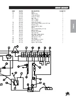
Страница 32: ...30 Parts ENGINEANDPUMPS DRAWING ...

Страница 33: ...mp 1 76 197 08 Seal Kit 1 13 18 350 Elbow 3 8 1 14 23 191 Elbow 1 15 30 029 CenteringArm Mount 1 16 30 102 Eaton Closed Loop Pump 1 17 30 082 IdlerArm 1 HMB 12 14 Machine Bushing 1 2 14GA HP 18 075 Cotter Pin 1 8 x 3 4 1 18 18 404 Adapter 1 19 48 049 Shift Arm Spacer 1 20 18 405 RunTee 1 21 14 266 Ball Bearing 1 HB 38 16 200 Bolt 3 8 16 x 2 1 HW 38 Washer 3 8 2 HN 38 16 Nut 3 8 16 1 22 48 109 Spri...

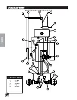
Страница 34: ...32 Parts ENGINEANDPUMPS DRAWING ...

Страница 35: ... 33 480 Pressure Switch 1 36 16 998 Hypro Spray Pump 1 HB 38 16 150 Bolt 3 8 16 x 11 2 2 HNFL 38 16 Flange Lock Nut 3 8 16 2 37 30 197 V Belt 1 38 HBM 10 1 25 30 Bolt 10 1 25 x 30 3 HWLM 10 10 Lock Washer 3 39 30 206 Pulley 1 40 33 494 Male Elbow 1 41 16 880 Nipple 2 42 18 390 Tee 1 43 16 182 90 Elbow 1 44 30 042 02 Air Cleaner 1 30 042 05 Element 1 45 10 389 Plug 1 46 23 145 Oring 1 47 30 042 14 ...

Страница 36: ...34 Parts COOLERANDEXHAUSTDRAWING ...

Страница 37: ...B 38 16 275 Bolt 3 8 16 x 23 4 4 HNFL 38 16 Flange Lock Nut 3 8 16 4 12 30 105 Thermal Transfer Heat Exchanger 1 13 18 107 Pipe Thread Reducer 1 14 18 402 3 4 x 90 Hose Barb 1 15 Radiator 1 16 18 408 Tube End Reducer 1 17 18 397 90 Hose Barb 1 18 30 042 Kubota 33 5 HP Diesel Engine 1 19 Hardware 20 42 004 02 Air Cleaner Cap 1 21 30 042 03 Clamp 1 22 30 042 02 Air Cleaner Body 1 30 042 05 Element 1...

Страница 38: ...36 Parts REARWHEELDRIVEDRAWING ...

Страница 39: ...6 17 615 Boom Tube 2 7 17 614 Boom Spacer 2 8 HB 516 18 100 Bolt 5 16 18 x 1 12 HW 516 18 Washer 5 16 12 HNFL 516 18 Flange Nut 5 16 18 12 9 HNFL 12 13 Flange Nut 1 2 13 8 10 20 555 U bolt 4 11 16 557 Square Cap 2 12 30 250 Main Frame 1 13 20 657 Mud Flap 2 14 HB 14 20 075 Bolt 1 4 20 x 3 4 6 HWF 14 Fender Washer 1 4 6 HNFL 14 20 Flange Nut 1 4 20 6 15 30 290 Rear Mud Flap Bracket 2 HB 516 18 100 ...

Страница 40: ...38 Parts TANKDRAWING ...

Страница 41: ...1 8828 16 Foam Tape 1 20 33 480 Pressure Switch 1 21 16 161 Fitting 3 22 16 825 Hex Bushing 1 23 33 494 Male Elbow 2 8954 44 Clear Hose 1 18 116 Hose Clamp 2 24 16 998 Hypro Pump 1 25 16 156 Elbow 2 26 16 851 1 Close Nipple 1 27 18 372 3 Way Valve 1 18 372 01 Handle 1 28 16 180 Quick Coupler Male 1 29 16 935 Quick Coupler Cap 1 30 HB 38 16 275 Bolt 3 8 16 x 23 4 4 HW 38 Washer 3 8 4 HNFL 38 16 Fla...

Страница 42: ...40 Parts TURBO QUADAGITATORDRAWING ...

Страница 43: ...RT DESCRIPTION QUANTITY 1 16 036 Agitator Jet Includes one each 1 8 5 53 and 3 16 orifices 4 2 16 173 Reducer 3 4 x 1 2 4 3 16 158 Close Nipple 3 4 x 3 4 2 4 16 157 Female Pipe Thread Tee 3 4 x 3 4 x 3 4 3 5 16 172 Nylon Nipple 3 4 NPT x 31 2 1 ...

Страница 44: ...42 Parts 15 301ORBITROLDRAWING ...

Страница 45: ...08 Drive Pin 1 15 Spool 1 16 Spring Retaining Ring 1 17 10 576 05 Gerotor 1 18 O Ring 1 19 Seal Ring 1 20 15 301 03 End Cap 1 21 10 576 06 Cap Screw 7 15 301 01 Seal Kit 1 15 301 15 Centering Spring Kit 1 15 301ORBITROLSPECIFICATIONS Inlet Relief Valve Setting 1020 psi 70 bar Nominal Flow 3 gpm 11 lpm Displacement 4 50 cu in R 73 8 cu cm R Check Valve for Manual Steering Yes Inlet Pressure Rating ...

Страница 46: ...nical Seal Silicon Carbide 1 9 16 998 06 Mounting Flange 1 10 16 998 07 Bolt 11 16 966 06 Slinger Ring 1 12 16 966 10 Ball Bearing 2 13 16 998 09 Pump Shaft 1 14 16 822 20 Key 1 15 16 966 13 Bearing Retainer 1 16 16 994 01 Clutch 1 16 998 12 Pump Only 16 967 Silicone Carbon Seal Kit When servicing the spray pump or filter all control valves must be shut off if there is liquid in the tank ...

Страница 47: ... 197 01 Front Plate 1 3 Washer 4 4 76 197 06 Cap Screw 8 5 76 197 07 Retaining Ring 1 6 Shaft Seal 1 7 33 061 15 Washer 1 8 O Ring 2 9 Backup Gasket 1 10 Seal 1 11 Wear Plate 1 12 76 197 04 Shaft comes with Idler Gear 1 13 76 197 02 Back Plate 1 14 Plug 1 76 197 08 Seal Kit ...

Страница 48: ...46 Parts 30 102EATONPUMPDRAWING ...

Страница 49: ...O Ring 1 19 Retaining Ring 1 20 33 058 41 Dump ValveActuator 1 21 Quad Ring 1 22 33 058 34 Key 1 23 Seal Sub Assembly 2 24 33 058 32 Plug S A 2 O Ring 2 25 33 058 19 Plug Sub Assembly 1 O Ring 1 26 Control Housing Gasket 1 27 33 058 40 Control Valve Orifice 1 28 33 058 37 Servo Control Assembly 1 29 33 058 29 Nut 1 30 33 058 30 Lockwasher 1 31 33 058 36 Control Arm 1 32 33 058 15 Cap Screw 6 33 33...

Страница 50: ...48 Parts 30 102EATONPUMPDRAWING ...

Страница 51: ...3 058 10 Thrust Race 2 51 33 058 11 Thrust Bearing 1 52 33 058 31 Washer 1 53 33 058 52 Shaft Seal 1 54 Retaining Ring 1 55 33 058 28 Drive Shaft 1 56 33 058 17 Housing Assembly 1 57 33 058 18 Bearing Press Fit 1 58 33 058 33 Plug S A 1 O Ring 1 59 33 058 07 Cover Plate 1 60 33 058 51 Control Valve Orifice 2 33 058 01 Seal Repair Kit NS 23 145 Oring between gear pump and hydro pump 1 ...

Страница 52: ...50 Parts 30 101EATONMOTORDRAWING ...

Страница 53: ... 7 Shaft Face Seal 1 8 30 101 03 Wear Plate 1 9 30 101 04 Main Drive 1 10 30 101 05 Geroler 1 11 30 101 06 Valve Plate 1 12 14 207 ValveDrive 1 13 14 208 Valve 1 14 30 101 07 Balance Ring 1 15 14 210 Balance Ring Pin 2 16 14 209 Compression Spring 2 17 Inner Face Seal 1 18 Outer Face Seal 1 19 30 101 08 Valve Housing 1 20 30 101 09 Plug Assembly 1 O ring 1 21 30 101 10 Cap Screw 4 30 101 11 Seal K...

Страница 54: ...52 Parts 30 099 AUBURN POWERWHEEL DRAWING ...

Страница 55: ...2 Bearing Cone 1 13 Retaining Ring Kit 1 14 30 099 04 Retaining Ring 2 15 Washer 2 16 30 099 03 Disengage Spring 1 17 Ring Gear 1 18 CarrierAssembly 1 19 Sun Gear 1 20 Retaining Ring 1 21 30 099 07 Thrust Washer 1 22 Disengage Plunger 1 23 O ring 1 24 LargeCover 1 25 Hex Head Bolt 8 26 Magnetic Plug 1 27 Disengage Cover 1 28 Hex Head Bolt 2 29 Quick Disconnect Gasket 1 30 Quick Disconnect Assembly...

Страница 56: ...54 Accessories 3182PLUMBINGDRAWING RAVEN440 15 818 75 Fitting O ring 15 817 50 Fitting O ring ...

Страница 57: ...x 1 Female Pipe thread Fitting 1 18 15 740 50 Series Clamp 5 19 15 738 Flanged Ball Valve 2 20 15 825 50 Male Quick Coupler 1 21 8897 60 11 4 Discharge Hose 60 1 18 116 Hose Clamp 2 22 16 998 Hypro Spray Pump 1 23 16 156 Elbow 2 24 33 494 Male Elbow 1 25 16 825 Hex Bushing 1 26 16 161 Fitting 3 27 8897 36 11 4 Discharge Hose 36 1 18 116 Hose Clamp 2 28 16 935 Quick Coupler Cap 1 29 16 180 Quick Co...

Страница 58: ...56 Accessories 3184PLUMBINGDRAWING RAVEN203 15 818 75 Fitting O ring 15 817 50 Fitting O ring ...

Страница 59: ...Valve 2 20 15 825 50 Male Quick Coupler 1 21 8897 64 11 4 Discharge Hose 64 1 18 116 Hose Clamp 2 22 16 998 Hypro Spray Pump 1 23 33 494 Male Elbow 1 8954 30 Clear Hose 1 24 16 825 Hex Bushing 1 25 16 161 Fitting 3 26 8897 24 11 4 Discharge Hose 24 1 18 116 Hose Clamp 2 27 16 935 Quick Coupler Cap 1 28 16 180 Quick Coupler Male 1 29 18 372 3 Way Valve 1 18 372 01 Handle 1 30 8897 36 11 4 Discharge...

Страница 60: ...58 Accessories 3185 3186 PLUMBING DRAWING ENVIZIO PRO II SHARP SHOOTER 15 818 75 Fitting O ring 15 817 50 Fitting O ring ...

Страница 61: ...18 30 168 04 SharpShooter Presser Sensor Assembly 1 19 15 777 Gauge Port Flange 1 20 30 177 Envizio Pro II Pressure Transducer 1 21 18 373 Flow Meter 1 18 373 01 Sensor 1 22 15 744 75 Hose Barb 1 23 8897 60 11 4 Discharge Hose x 60 1 18 116 Hose Clamp 2 24 15 737 Flanged Strainer 1 16 968 05 Screen 80 mesh 1 25 16 998 Hypro Pump 1 26 16 161 Fitting 3 27 8897 36 Discharge Hose 1 18 116 Hose Clamp 2...

Страница 62: ...60 Accessories 3187 3188PLUMBINGDRAWING RAVEN400 SHARPSHOOTER 15 818 75 Fitting O ring 15 817 50 Fitting O ring ...

Страница 63: ... Barb 2 14 16 281 Liquid Filled Gauge 2 15 HB 38 16 550 Bolt 3 8 16 x 51 2 2 HNFL 38 16 Flange Lock Nut 3 8 16 2 16 15 737 Flanged Strainer 1 16 968 05 Screen 80 mesh 1 17 15 735 50 x 1 Female Pipe thread Fitting 1 18 15 740 50 Series Clamp 7 19 15 738 Flanged Ball Valve 2 20 15 825 50 Male Quick Coupler 1 21 8897 60 11 4 Discharge Hose 60 1 18 116 Hose Clamp 2 22 16 998 Hypro Spray Pump 1 23 16 1...

Страница 64: ...62 Accessories 3187 3188PLUMBINGDRAWING RAVEN400 SHARPSHOOTER 15 818 75 Fitting O ring 15 817 50 Fitting O ring ...

Страница 65: ...3 30 168 04 SharpShooter Pressure Sensor 1 44 17 615 Universal Boom Support 2 45 16 557 Square Cap 2 46 17 537 Square U bolt 2 47 30 167 Mounting Strap 1 48 30 173 GPS Plate 1 49 30 172 Fiberglass Cover 1 50 10 389 Plug 1 51 15 869 1 Hose Barb Outlet 1 15 553 01 Clip 1 15 553 02 O ring 1 52 16 961 Adapter1 1 53 16 962 Coupler 1 1 54 8896 72 1 Discharge Hose x 72 1 18 222 Hose Clamp 2 55 15 808 50 ...

Страница 66: ...64 Accessories CONTROLS3182SYSTEMDRAWING RAVEN 440 ...

Страница 67: ...ount 1 9 20 540 Ram Mount 1 10 50 400 Grommet 1 11 20 596 Dash Board 1 12 33 271 Fuse Block 1 13 33 508 Auto Blade Type Fuse 15 amp 1 14 33 562 Auto Blade Type Fuse 40 amp 1 15 15 369 Console Control Cable 1 16 16 524 Motorized Control Valve 1 17 15 743 Manifold Valve 1 18 18 373 Flow Meter 1 19 33 509 Master Boom Floor Switch 1 20 10 408 01 Phoenix 10 GPS 1 10 408 02 Cable 1 21 12 017 Hour Meter ...

Страница 68: ...66 Accessories CONTROLS3184SYSTEMDRAWING RAVEN 203 ...

Страница 69: ...5 AMP 1 8 16 895 Pressure Switch 1 9 20 546 Console Mount 1 10 20 540 Ram Mount 1 11 50 400 Grommet 1 12 20 596 Dash Board 1 13 33 271 Fuse Block 1 14 33 508 Auto Blade Type Fuse 15 amp 1 15 33 562 Auto Blade Type Fuse 40 Amp 1 16 16 958 04 Cable Assembly 8ft Enclosure Hook Up 1 17 16 902 Cable Assembly 72 Solenoid Hook Up 1 18 15 776 Tee 1 19 15 743 Manifold Valve 1 20 16 524 Motorized Control Va...

Страница 70: ...68 Accessories WIRING 3185 3186 SYSTEM ENVIZIO PRO II SHARP SHOOTER W RATE SYNC ...

Страница 71: ...1 7 See Valve Nozzle Drawing 8 30 174 12 Product Cable 1 9 30 164 Tapped Reducer Tee 1 10 30 168 04 SharpShooter Pressure Sensor 1 11 30 176 3 Console Cable 1 12 30 264 SharpShooter with Rate Sync 1 13 30 173 GPS Plate 1 14 30 220 SwitchPro Kit 1 15 30 172 Fiberglass Cover 1 8803 48 Trim 48 1 18 134 Grommet 1 16 30 218 02 GPSAntenna 1 17 30 218 03 GPS Cable 1 18 30 218 01 Envizio Pro II Console 1 ...

Страница 72: ...70 Accessories WIRING3187 3188SYSTEM RAVEN440 SHARPSHOOTER ...

Страница 73: ...ck 1 9035 Blade Fuse 1amp 1 13 33 508 Auto Blade Type Fuse 15 amp 2 14 33 273 Auto Blade Type Fuse 30 amp 1 15 15 369 Console Control Cable 1 16 16 524 Motorized Control Valve 1 17 15 775 Reducer Tee 1 18 30 164 Tapped Reducer 2 19 30 168 04 SharpShooter Pressure Sensor 1 20 See Valve Nozzle Drawing 21 18 373 Flow Meter 1 22 33 509 Master Boom Floor Switch 1 23 12 017 Hour Meter 1 24 30 264 SharpS...

Страница 74: ...n both directions Motor must stop when coupler shaft CAM releases printed circuit board button When reassembling valve grease both sealing sur faces of coupler shaft Insert coupler shaft into Iso flange and be sure seal properly seats on shaft In stall motor on valve body and apply silicon sealant to mounting holes Reassemble remaining items as shown in parts diagram REF PART DESCRIPTION QUANTITY ...

Страница 75: ... REF PART DESCRIPTION QUANTITY 1 15 737 01 Strainer Head 75 Series 1 2 16 968 03 50 Mesh Strainer 1 16 968 05 80 Mesh Strainer 1 3 14 521 02 EPDM Gasket 1 4 14 521 03 Bowl 1 NPT 1 5 14 521 04 EPDM Rubber gasket 1 6 14 521 05 Cap 1 ...

Страница 76: ...74 Accessories 15 743MANIFOLDVALVEDRAWING ...

Страница 77: ...e 1 6 15 517 11 Thrust Washer Teflon 1 7 15 552 27 Stem Stainless Steel 1 8 15 552 05 O ring Viton 3 9 15 517 16 Body Nylon 1 10 Lock Nut Stainless Steel 2 11 15 743 04 Ball Polypropylene 1 12 15 552 13 Gasket Viton 2 13 15 517 19 Seal Teflon 2 14 15 517 20 O ring Viton 2 15 15 743 01 End Cap 1 16 15 743 02 75 Tee Body 1 17 15 743 06 Screw SS 4 18 15 743 03 Mounting RailAluminum 1 15 552 10 Spare ...

Страница 78: ...76 Accessories 17 58020 HEAVYBOOM ...

Страница 79: ...d 2 HBFL 516 18 075 Bolt 5 16 18 x 3 4 4 HNFL 516 18 Flange Lock Nut 5 16 18 4 12 17 532 Right Boom Arm 1 14 33 506 Body see nozzle drawing 12 HB 516 18 100 Bolt 5 16 18 x 1 12 HNFL 516 18 Flange Lock Nut 5 16 18 12 15 17 632 Boom Hinge Complete 2 HB 38 16 100 Bolt 3 8 16 x 1 8 HNFL 38 16 Lock Nut 3 8 16 8 HB 516 18 100 Bolt 5 16 18 x 1 8 HW 516 Washer 5 16 8 HNFL 516 18 Flange Lock Nut 5 16 18 8 ...

Страница 80: ...78 Accessories 17 58020 BOOMDRAWING ...

Страница 81: ... HB 516 18 100 Bolt 5 16 16 x 1 8 HW 516 Flat Washer 5 16 8 HNTL 516 18 Lock Nut 5 16 18 8 31 17 587 Boom Lock 2 32 42 116 Rubber Insert 4 33 8803 2 75 Trim Lace 23 4 2 34 17 588 Lock Hinge RH 1 35 17 597 Torsion Spring RH 1 36 17 589 Limit Hinge RH 1 37 HB 516 18 100 Bolt 5 16 16 x 1 2 HNFL 516 18 Flange Lock Nut 5 16 18 2 38 17 593 Limit Hinge LH 1 17 598 Torsion Spring LH 1 39 17 592 Lock Hinge...

Страница 82: ...4 33 506 Nozzle body see nozzle drawing 11 5 18 415 3 4 Hose Barb 1 6 8887 2 5 Orange PVC Hose 3 4 x 21 2 1 18 040 Hose Clamp 2 7 8887 15 5 Orange PVC Hose 3 4 x 151 2 1 18 040 Hose Clamp 2 8 16 281 Gauge 1 9 17 602 Nozzle Body 1 10 8887 5 Orange PVC Hose 3 4 x 5 1 18 040 Hose Clamp 2 11 16 800 Strainer 1 12 16 921 Nozzle 1 13 8887 13 Orange PVC Hose 3 4 x 13 1 18 040 Hose Clamp 2 ...

Страница 83: ...4 33 506 Nozzle body see nozzle drawing 12 5 18 415 3 4 Hose Barb 1 6 8887 2 5 Orange PVC Hose 3 4 x 21 2 1 18 040 Hose Clamp 2 7 8887 15 5 Orange PVC Hose 3 4 x 151 2 1 18 040 Hose Clamp 2 8 16 281 Gauge 1 9 17 602 Nozzle Body 1 10 8887 5 Orange PVC Hose 3 4 x 5 1 18 040 Hose Clamp 2 11 16 800 Strainer 1 12 16 921 Nozzle 1 13 8887 13 Orange PVC Hose 3 4 x 13 1 18 040 Hose Clamp 2 ...

Страница 84: ...82 Accessories 17 585 18 HEAVYBOOM ...

Страница 85: ...x 11 2 2 HNFL 38 16 Flange Lock Nut 3 8 16 2 15 17 589 Limit Hinge Rh 1 16 17 596 Hinge Pin w Spacer 2 HP 18 100 Cotter Pin 1 8 x 1 2 HB 516 18 100 Bolt 5 16 18 x 1 2 HNFL 516 18 Flange Lock Nut 5 16 18 2 17 17 528 Boom Center 1 19 18 234 1 Bushing part of 30 214 2 20 HBFL 516 18 075 Bolt 5 16 18 x 3 4 8 HNFL 516 18 Flange Lock Nut 5 16 18 8 21 17 541 Boom End Guard 2 HBFL 516 18 075 Bolt 5 16 18 ...

Страница 86: ...84 Accessories 17 585 18 HEAVYBOOM ...

Страница 87: ... 3 8 16 x 3 2 HNTL 38 16 Lock Nut 3 8 16 2 34 HB 12 13 300 Bolt 1 2 13 x 3 2 HNTL 12 13 Lock Nut 1 2 13 2 35 17 593 Limit Hinge LH 1 17 598 Torsion Spring LH 1 36 17 592 Lock Hinge LH 1 37 HB 38 16 300 Bolt 3 8 16 x 3 2 HW 38 Washer 3 8 2 HNTL 38 16 Lock Nut 3 8 16 2 38 17 619 Tube Cap 4 39 30 258 Ribbed 1 Plug 10 ...

Страница 88: ... 33 554 Nozzle White XR11008 VS 1 8 16 802 Strainer 3 Quantity is per nozzle body For 20 booms multiply quantity by 12 Quantity is per nozzle body For 18 booms multiply quantity by 11 Nozzles are located 20 51 cm apart on the right left and center tubes Nozzles are 20 high off ground For reordering Nozzle Kits the following numbers apply 33 540 Triple Nozzle Kit for 18 Booms 33 542 Triple Nozzle K...

Страница 89: ...udes items 2 2 30 168 12 CRII SaddleAssembly 1 3 30 168 20 O ring 1 4 30 168 26 Valve Body 1 5 30 168 18 O ring 1 6 30 168 25 Fly Nut 1 7 30 168 17 Plunger 1 8 30 168 19 O ring 1 9 30 168 21 Coil 1 10 30 168 13 Combo Jet SR110 10 1 11 30 168 14 Combo Jet MR110 10 1 12 30 168 22 End Body Assembly 1 13 30 168 15 Lock U Clip 1 ...

Страница 90: ...88 Accessories 30 010ELECTRICHOSEREELDRAWING ...

Страница 91: ...embly 1 10 HB 516 18 075 Bolt 5 16 18 x 3 4 8 11 16 906 26 Pipe Cap 3 4 1 12 HWL 516 Lockwasher 5 16 8 13 Motor 12VDC 1 14 HW 516 Washer 5 16 4 16 HNTL 516 18 Lock Nut 5 16 18 4 17 HB 516 18 100 Bolt 5 16 18 x 1 4 18 16 906 17 Key 1 19 Set Screw 2 20 16 906 29 Pinion 1 21 HNTL 38 16 Lock Nut 3 8 16 4 22 16 906 18 Frame Assembly 1 23 16 906 08 Mounting Pillow Block Bottom 2 24 16 906 24 Bearing 2 2...

Страница 92: ...NINSTRUCTIONS Route wire harness along side of tank and over to fuse block taking care to stay clear of moving parts or hot engine components Cut off excess wire and strip back 3 8 Place one 8963 heat shrink 1 4 x 11 4 on each wire before crimping 8901 slide on connectors to the red and white wires Connect the two wires to the fuse block first the red to the positive and the white to the negative ...

Страница 93: ...ide 1 9 HWL 516 Lockwasher 5 16 8 10 HB 516 18 075 Bolt 5 16 18 x 3 4 8 11 16 129 09 Crank Assembly 3 4 1 12 16 129 10 Brake Assembly 3 4 1 13 HNTL 38 16 Lock Nut 3 8 16 4 14 HNTL 516 18 Lock Nut 5 16 18 2 15 16 129 08 Lock Pin Assembly 1 16 HB 516 18 075 Bolt 5 16 18 x 3 4 2 HW 516 Washer 5 16 2 17 16 129 07 Frame Assembly 1 18 16 906 08 Mounting Pillow Block Bottom 2 19 16 906 24 Bearing 2 20 16...

Страница 94: ...92 Accessories HOSEREELMOUNT DRAWING ...

Страница 95: ...ll valve by the manifold valve and place the 15 749 Hose Barb Tighten clamp 8 Route hose from the hose barb on the ball valve to the barb fitting on the side of the hose reel Hold in place with the two 18 040 clamps 9 Be sure all clamps and hardware are tight before using HOSE REEL ADJUSTMENTS OPERATIONAL CHECK 1 Pull hose off drum at least one full revolution A clicking noise should be heard from...

Страница 96: ...94 Accessories 30 004FOAMMARKERDRAWING WIRINGDRAWING ...

Страница 97: ... 2 5 HN 14 20 075 Hex Bolt 1 4 20 x 3 4 2 HBFL 14 20 Flange Lock Nut 1 4 20 2 6 14 291 02 Foamer Tank 1 7 14 284 02 Cap Assembly 1 8 Blue Tube 1 9 Clear Tube 1 10 14 291 03 Compressor Only 1 14 291 01 Black Cover 1 14 291 Foamer includes parts 1 WIRING PARTS LIST REF PART DESCRIPTION QUANTITY 1 14 291 03 Compressor 1 2 15 504 04 Wiring Harness 1 3 14 291 05 Switch Box 1 33 508 Fuse 1 15 506 02 Cen...

Страница 98: ...96 Accessories 30 004FOAMMARKERDRAWING ...

Страница 99: ...r the back of the spray tank so it can be connected to the compressor CONNECTINGTHECAPASSEMBLY Connect the blue tube to the tank cap connector which is also connected to the large blue tube which hangs below the cap This is the soap outlet tube Connect the clear tube to the other connector on the tank cap This is the air input tube Tighten connectors hand tight assembly tank cap onto tank HOSES Be...

Страница 100: ...98 Accessories FOAMER NOZZLEMOUNT HOSEGUARDMOUNTDRAWING ...

Страница 101: ...g along underside of main frame using tie downs as necessary 7 Install opposite ends of air liquid tubes to compressor again cutting back the oversleeve approximately 2 5 cm and inserting blue and clear tubes for the left boom section into the tubing connectors Ref A on the right side of compressor as far as possible 8 Follow the same steps for the right boom tubing Notice the right boom is insert...

Страница 102: ...ng 1 2 14 291 02 Tank 1 3 14 291 01 Black Cover 1 14 536 Compressor Complete 1 4 14 284 02 CapAssembly 1 5 14 291 04 Tank Bracket 1 6 14 291 05 Double Switch Box 1 7 15 511 Foam Nozzle 1 8 15 510 01 Nozzle Mounting Rod 1 9 16 987 Foam Nozzle Mounting Kit 1 14 536 Compressor Subassembly ...

Страница 103: ...101 Accessories NOTES ...

Страница 104: ... Foam Nozzle Inlet Body 1 15 511 02 Foam Sponge 1 15 511 10 Plastic Screen 1 2 Hose Clamp 1 3 Drop Tube 1 4 15 511 08 Long Foam Sponge 1 5 15 511 09 Stainless Steel Screen 1 6 Hose Clamp 1 7 14 284 09 Foam Nozzle Reducer 1 NS 15 510 01 Nozzle Mounting Rods 2 15 511 07 Foam Nozzle Sub Assembly ...

Страница 105: ...machine 1 5 16 961 1 Adapter Quick Coupler already on machine 1 6 16 851 1 Nipple 1 7 18 448 1 Ball Valve 1 1 Thoroughly flush the service line upstream of the meter to remove dirt and debris 2 The DLJ Meter is for use only with COLD WATER up to 122 F 50 C 3 Slowly open any upstream valves to prevent damage to the meter Gallons to Cubic feet Conversion Multiply gallons reading by 0 1337 to get cub...

Страница 106: ...104 Accessories 30 006FRESHWATERTANKDRAWING ...

Страница 107: ... Wash Tank mounts on the rear of all the machines 2 The Bracket is already attached to the SUper Boom center boom post 3 Install the nipple Ref 2 elbow Ref 3 and spigot Ref 4 into the bottom of wash tank Ref 1 Use thread tape on all threads 4 Mount the tank onto the mount bracket using four 5 16 x 3 4 bolts washers and lockwashers TIghten 5 Rinse tank with clear water and check for leaks around fi...

Страница 108: ... Elbow 1 5 15 620 CleanloadAssembly 1 6 8897 38 11 4 Discharge Hose 38 1 18 116 Hose Clamp 2 7 17 535 Clean Load Mount part of boom 1 8 16 945 Fitting part of tank 1 9 16 971 45 Elbow part of tank 1 10 16 161 Fitting 1 11 16 159 Hose Barb 1 12 14 604 Loom Clamp Mount 1 13 HB 516 18 100 Bolt 5 16 18 x 1 2 HNFL 516 18 Flange Lock Nut 5 16 18 2 14 HLC A 200 Loom Clamp 1 15 Center Boom ...

Страница 109: ...IQUID AND OR POWDERED CHEMICAL WITH SUCTION LANCE Note Lance suction is dependent upon eductor pressure and flow For best results use highest pressure available up to 150 PSI maximum 8 Insert lance body with o ring into eductor until the o ring is sealed 9 Use the free end of the lance to pierce bag or container to vacuum powdered or liquid chemical 10 Rinse lance Place lance end into a clean cont...

Страница 110: ...108 Accessories 15 620CHEMICALCLEANLOAD PARTSDRAWING ...

Страница 111: ...langed 1 4 20 2 17 Bolt 1 4 20 x 3 4 SS 2 18 15 620 01 Frame Back Mount 1 19 Screw 10 24 x 375 2 20 15 620 11 Elbow 1 2 2 21 15 620 10 Valve SS Tank Rinse 1 22 15 620 09 HB 1 2 MNPT x 1 2 HB 2 23 15 620 05 HB Tee 1 2 MNPT to 1 2 HB 1 24 Tee 1 2 FNPT 1 25 Nipple 1 2 1 26 15 620 20 Gasket 1 1 27 Valve Bottle Rinse Base Assy 1 28 Bottle Rinse Head 1 29 Valve 1 2 1 30 HB Elbow 1 2 MNPT x 3 8 HB 1 31 H...

Страница 112: ...4 1 FTP Elbow 1 4 16 158 Close Nipple 1 5 16 150 Double Thread Fitting 1 6 16 172 4 Nipple 1 7 15 834 Tank Rinsing Nozzle 1 8 16 163 Reducer Bushing 1 Drill 1 3 4 hole 5 from outside edge of cover Install Tank Rinsing kit as shown with the Double Thread Fitting Ref 5 going into the cover Basket Must be removed During Use ...

Страница 113: ...ing E 25 286 Decal Pinch Point F 25 298 Decal Warning Hot G 25 321 Decal Refuel w Diesel H 25 356 Decal Tire Pressure 20psi I 25 371 Decal Diesel J 25 372 Decal 4 Star K 25 375 Decal 94 dBA L 25 380 Decal Tire Pressure 30psi M 27 077 Decal Smithco N 27 093 Decal Hydraulic Oil Level O 30 016 Decal Spray Star 3180 P 20 545 Decal Dashboard Q 30 019 Decal Site Gauge R 30 157 Decal Control Panel S 30 1...

Страница 114: ...ring Orbital Motor 15 301 01 Seal Kit 30 101 Wheel Motors 30 101 11 Seal Kit 30 102 Hydrostatic Pump 33 058 01 Seal Kit 76 197 Gear Pump 76 197 08 Seal Kit 15 839 Hydraulic Cylinder steering 14 531 Seal Kit FLUIDS Engine Oil SAE 10W 40 API Service SJ or higher Motor Oil Hydraulic Fluid SAE 10W 40 API Service SJ or higher Motor Oil Radiator 1 06 Gal 50 50Antifreeze water mixture OTHERPARTS 16 953 H...

Страница 115: ...afe operation of this product at your location Instructions for Obtaining Warranty Service You are responsible for notifying the Authorized Smithco Products Distributor from whom you purchased the Product as soon as you believe a warrantable condition exists and not later than 30 days from discovery of the condition If you need help locating an Authorized Smithco Distributor or if you have questio...

Страница 116: ...acturers if inspection by the original component manufacturer indicates that failure was due to normal wear and tear expected consumption through use or improper care or service Other Legal Disclaimers The above remedy for product defects through repair or replacement by an authorized Smithco distributor or dealer is the purchaser s sole remedy for any defect This warranty gives you specific legal...

Отзывы: