


9
Ser
vice
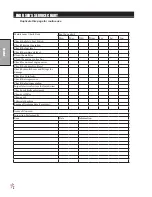
ADJUSTMENTS
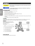
PARK BRAKE
Turn knob clockwise on end of park brake to tighten. Turn it counter clockwise to loosen. If finer adjustment is
needed turn clevis on brake cable to adjust length of cable.
SPRAY PUMP
Located to the rear and right of the engine. Should have approximately
1
/
2
" (13mm) of deflection in the center
of the top strand. Loosen two
9
/
16
x 1
3
/
4
bolts. Slide pump to the rear to desired tension. Tighten two
3
/
8
x 1
1
/
2
bolts.
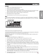
SPEED CALIBRATION NUMBERS
The speed calibration numbers for Spray Star 1008 with GPS is 785. Metric is 205.
MASTER BOOM SWITCH (FOOT SWITCH FOR SPRAY STAR 1008)
The master boom switch, located on the left floorboard is used to override the master switch on the computer
console of the spray systems. By pushing down it will turn on/off the booms.
For the 440 System
the Master
Switch on the computer
must be off
for the master boom control switch to work.
TO ENGAGE:
1. Flip rocker switch ‘On’ (green light).
2. Obtain desired speed with foot pedal.
3. Step on foot switch to lock speed.
4. Push foot switch again to disengage.
SPRAY BOSS CONTROL HANDLE
This lever located on the left side of the seat engages and disengages the speed boss. Forward is engage
and all the way back is disengage. When the lever is engaged it sets a stop for the accelerator. The accelera
-
tor pedal must be used to maintain this speed. To adjust speed use the knob on the end of the lever, counter
clockwise increases speed and clockwise decreases speed. Disengage the lever and you will have full accel
-
erator pedal range.
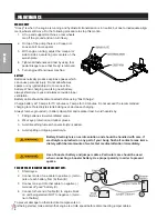
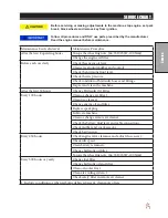
FLOW METER MAINTENANCE AND ADJUSTMENT (440 SYSTEM ONLY)
1. Remove Flow meter from Sprayer, brush away any debris and flush with clean water to remove any
foreign material.
2. Remove the retaining rings carefully. Remove the bearing hub, turbine hub, and turbine from inside flow
meter.
3. Clean the turbine and hubs of metal filings and any other foreign material. Use pressurized air to blow
metal filings and debris out of both hub and turbine. Check blades for wear. Holding turbine and bearing
in your hand, spin turbine. It should spin freely with very little drag.
4. If bearing hub stud is adjusted or replaced, verify the turbine fit before reassembling. Put turbine hub
and retaining ring in place. Put bearing hub with turbine against turbine hub inside the flow meter
housing. Put the retaining ring into the groove, to lock bearing hub in place. Spin turbine by blowing on
it. Tighten bearing hub stud until turbine stalls. Loosen the stud 1/3 turn. The turbine should spin freely.
5. Use a low pressure (5PSU) jet of air through flow meter in the direction of flow and again in opposite
direction to verify that the turbine spins freely. If there is drag, loosen the stud on the bearing hub 1/16
turn until the turbine spins freely.
6. If turbine spins freely and the cables have been checked, but the flow meter is not totalizing properly,
verify that the sensor assembly is threaded all the way into the flow meter body and the orientation
groove on top of the sensor is parallel with the flow meter body. If flow meter still does not totalize,
replace sensor assembly.
Содержание 10-100-D
Страница 13: ...11 NOTES ...
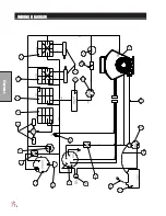
Страница 14: ...12 Diagrams WIRING DIAGRAM ...
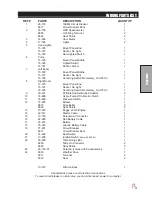
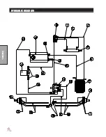
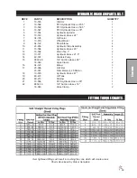
Страница 16: ...14 Diagrams HYDRAULIC DIAGRAM ...
Страница 18: ...16 Parts BODY FRAME DRAWING ...
Страница 20: ...18 Parts NOSE CONE DRAWING ...
Страница 22: ...20 Parts FRONT AXLE DRAWING ...
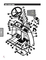
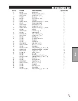
Страница 24: ...22 Parts SEAT CONSOLE AND ROPS DRAWING ...
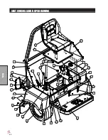
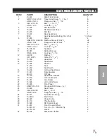
Страница 26: ...24 Parts FUEL TANK DRAWING ...
Страница 28: ...26 Parts OIL TANK OIL FILTER OIL COOLER DRAWING ...
Страница 30: ...28 Parts FOOT PEDAL LINKAGE DRAWING ...
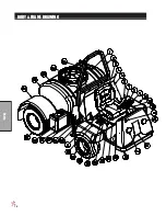
Страница 32: ...30 Parts PUMP DRAWING ...
Страница 34: ...32 Parts ENGINE DRAWING ...
Страница 36: ...34 Parts PARK BRAKE DRAWING ...
Страница 38: ...36 Parts REAR AXLE DRAWING ...
Страница 40: ...38 Parts TANK DRAWING TURBO QUAD AGITATOR DRAWING ...
Страница 42: ...40 Parts 10 576 ORBITROL DRAWING ...
Страница 56: ...54 Accessories 17 835 BOOM DRAWING ...
Страница 70: ...68 Accessories 16 906 ELECTRIC HOSE REEL DRAWING ...
Страница 72: ...70 Accessories 16 129 MANUAL HOSE REEL DRAWING ...
Страница 78: ...76 Accessories 10 378 FOAM MARKER FOR 1000 DRAWING WIRING DRAWING ...
Страница 80: ...78 Accessories 10 378 FOAM MARKER DRAWING ...
Страница 82: ...80 Accessories FOAMER NOZZLE MOUNT HOSE GUARD MOUNT DRAWING ...
Страница 84: ...82 Accessories 14 291 FOAMER REPLACEMENT PARTS ...
Страница 90: ...88 Accessories 15 620 CHEMICAL CLEAN LOAD DRAWING ...