background image

29

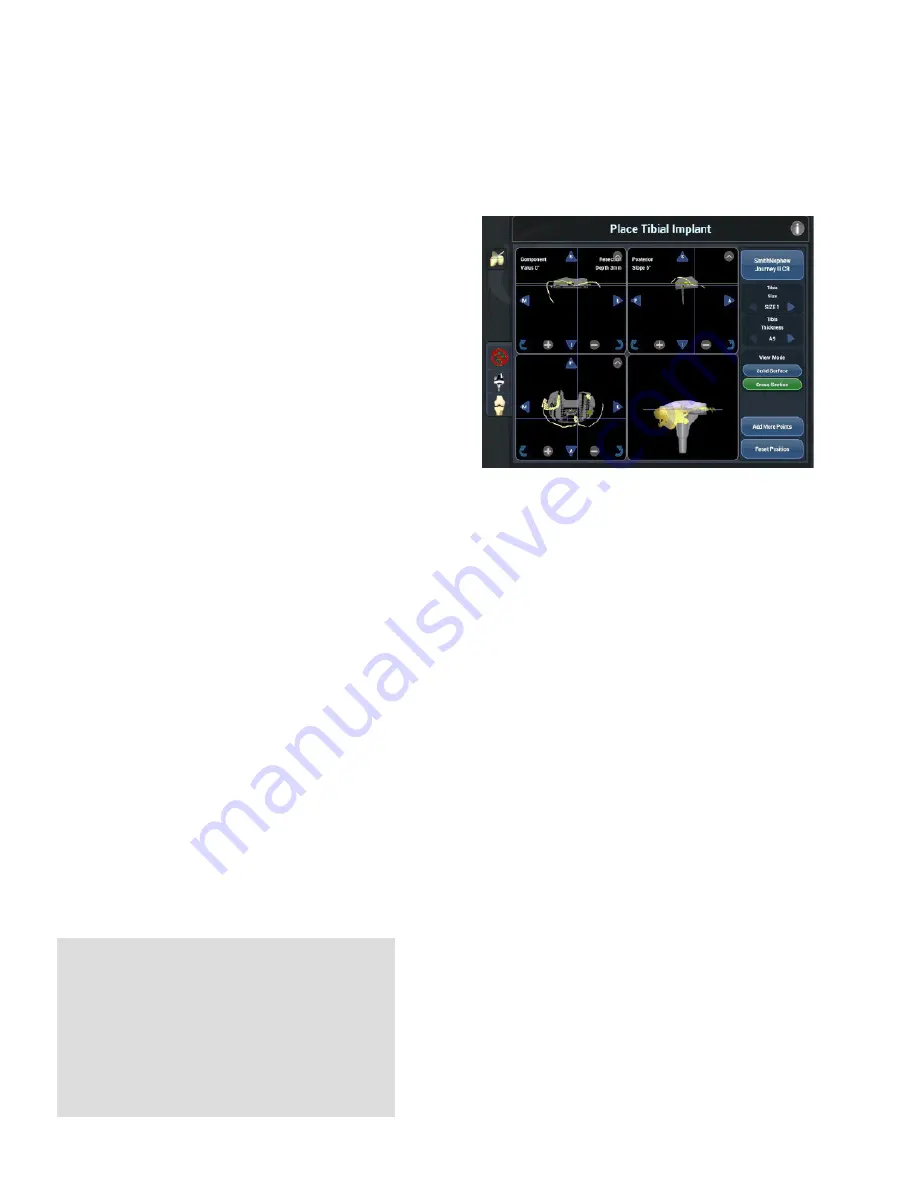
1.  Confirm the implant size using the transverse 

viewscreen (bottom left) and the tibia size up/

down button arrows in the right-hand control panel 

on the right side of the screen underneath the 

Tibia Size button.

2. Confirm the posterior slope, utilizing the sagittal 

view (upper right), NAVIO software will display 

the posterior slope within this viewscreen, which 

reflects the slope of the tibial implant component 

with respect to the mechanical axis defined during 

registration (Figure 45). The NAVIO software will 

start the tibia with either the amount of slope 

chosen in the surgical preferences section, or with 

a 3 degree initial posterior slope. 

3. The rotation of the tibial component is initialized 

to 0 degrees with respect to the tibial AP axis. 

This rotation can be further adjusted using the 

arrows active in that viewscreen (transverse) when 

selected. For total knee implants the rotation 

and ML placement of the tibial component is not 

constrained by NAVIO cut guides. The final implant 

rotation and the placement is performed with 

manual instrumentation.

4. The tibial component will default to the thinnest 

bearing. Thicker inserts can be chosen by 

changing the poly component, using the 

arrow buttons in the right console under the 

heading “Thickness.” The component position 

will default to place the tibia resection depth 

12 mm from the lateral plateau point. Using the 

arrows active in that screen, the user may move 

the component superior, decreasing resection 

depth. The resection depth displayed on the 

coronal view is based on the lower of the two 

plateau points collected on the tibia during the 

landmark collection stage. Refer to the Smith & 

Nephew JOURNEY™ II TKA surgical technique for 

recommendations on depth and slope of tibial 

resection. 

Figure 45. 

Confirm posterior slope is appropriate for patient - 

component will be placed initially at 3 degrees of posterior slope 

(upper right sagittal viewscreen). Confirm resection depth of the tibial 

component in the frontal view. Confirm medial lateral sizing and AP 

placement of the tibia component in the transverse view screen.

 6

 Implant Planning

If at any stage during Implant Planning, the 

user feels as if the current bone-morphed 

virtualization of the tibia is not sufficient, the 

user should press the Add Tibia Points button 

in the lower right portion of the screen and fill in 

the map in deficient areas. Continuing forward 

from the Tibia Free Collection screen will bring 

the user right back to the Implant Planning.

Содержание JOURNEY II BCS

Страница 1: ...Surgical Technique for use with the JOURNEY II BCS and JOURNEY II CR...

Страница 2: ...esponsibility of treating physicians to determine and utilize the appropriate products and techniques according to their own clinical judgment for each of their patients For more information on the NA...

Страница 3: ...hroplasty utilizing the NAVIO system This guide should be used in conjunction with not replacing the information contained within the NAVIO Surgical System for Total Knee Arthroplasty User s Manual th...

Страница 4: ...Positioning the System 9 1 System and Patient Setup 10 2 Bone Tracking Hardware 12 3 Surgical Preferences 14 4 Registration 17 5 Ligament Balancing 25 6 Implant Planning 26 7 Implant Planning Soft Ti...

Страница 5: ...FA and total knee arthroplasty TKA The NAVIO surgical system is indicated for use with cemented implants only Contraindications The NAVIO surgical system is not intended to be used on children pregnan...

Страница 6: ...or unicompartmental replacement This system is designed for use in patients in primary total knee replacement surgery where the anterior and posterior cruciate ligaments are incompetent and the collat...

Страница 7: ...emoval and prepare for rigid fixation of the NAVIO reusable cut guides which include the distal femur cut guide and tibia cut guide according to the component placement plan NAVIO Total Knee surgery c...

Страница 8: ...Adapter JOURNEY II Femur Drill Guide Femur Distal Cut Guides Small Medium Large Left Tibia Cut Guides Small Medium Large Right Tibia Cut Guides Small Medium Large Femur Stabilizers Small Medium Large...

Страница 9: ...been properly draped and prepped the sterile drape should be applied to the monitor according to the instructions for use provided by the monitor drape manufacturer Figure 5 An additional drape may b...

Страница 10: ...the NAVIO system touchscreen monitor with a sterile drape This will allow the surgeon to manipulate the touchscreen with gloved sterile finger control to augment footpedal control of the software The...

Страница 11: ...r to reliably assess joint stability it is crucial that all osteophytes are removed from the entire medial edge of both the femur and tibia Resect the deep menisco tibial layer of the medial capsule t...

Страница 12: ...lacement Engage the second screw with the bone through the tissue protector to ensure the pins are placed parallel to each other Slide the bone clamp with the clamp hardware oriented towards the optic...

Страница 13: ...he optical tracking camera and tracker frames allow for full uninterrupted visibility throughout the registration and cutting processes Advance to the Camera Orientation Adjustment screen in the workf...

Страница 14: ...Femur First 1 Ligament Stress Collection in extension and flexion See Ligament Balancing Section 5 2 Femur Component Placement See Implant Planning Section 6 3 Tibia Component Placement See Implant P...

Страница 15: ...epicondylar Axis 2 Femoral AP Axis 3 Posterior Condylar Axis For the tibia bone the following options are available to define the reference for computing the rotation of the component on the tibia Fig...

Страница 16: ...to guide the component placement Checkpoint Pins Checkpoint pins should be placed in both the femur and the tibia in positions where they will not be removed during bone removal Figure 17 These points...

Страница 17: ...Press and hold the right footpedal to collect the position Figure 18 When the bar on the bottom reads as fully green 100 release the footpedal to allow the software to automatically proceed to the ne...

Страница 18: ...rtant to take care to understand where these points are taken on the patient s bony anatomy so that they may be referenced properly during planning Using the point probe collect the following Figures...

Страница 19: ...n stage Figure 25 offers a visualization of the femoral mechanical and rotational axis previously collected blue lines as well as the four discrete femur landmark points collected above yellow dots On...

Страница 20: ...erence collection mark the medial and lateral epicondyles on the femur which will be used to create the medial lateral axis for the femur The AP axis is then derived from the femur mechanical axis and...

Страница 21: ...a line perpendicular to the mechanical axis from that point This joint line reference can be used during planning to place the implant component Tibial Condyle There are three tibial landmark points...

Страница 22: ...d during surgical preference selection there are four options to choose from to define the tibia rotational reference frame These rotational references are used during Implant Planning Section 6 for c...

Страница 23: ...xis will define the medial lateral axis of the patient s femur Transfer Femoral Mechanical Axis If the femur mechanical axis is selected the tibial rotational references are derived from the femur mec...

Страница 24: ...system to appropriately localize the implant during planning Define the anterior and medial edges of the condyle as far posterior as is accessible Map the intercondylar eminence along the axis of the...

Страница 25: ...e tightness in the medial or lateral compartment of the knee based on the stress collections when a distal femur component resection and tibial resection is to be made perpendicular to the mechanical...

Страница 26: ...y prepared bone by using Button A as shown in Figure 40b The cross section mode allows the user to drag a finger vertically over the highlighted window to fly through cross sectional slices of the fem...

Страница 27: ...tal and transverse view screen and by dragging vertically on the cross section view 4 In the top left coronal solid surface view if the surface map is behind the implant on the cement side as opposed...

Страница 28: ...AVIO software will indicate how much rotation the user is applying Keep in mind that the default value is 0 Tibia Placement The NAVIO software will attempt to provide a starting size and initial place...

Страница 29: ...an be chosen by changing the poly component using the arrow buttons in the right console under the heading Thickness The component position will default to place the tibia resection depth 12 mm from t...

Страница 30: ...ze changing arrows will size up right or size down left and display between the arrows the selected size This size will map to the manufacturer s provided labeling on the component boxes D Solid Surfa...

Страница 31: ...er to view the meshed virtual surface unobstructed C The tibia implant size changing arrows will size up right or size down left and display between the arrows the selected size This size will map to...

Страница 32: ...mplant Planning for translating and rotating the components with respect to the patient s virtualized joint Figure 48 Beneath these viewscreens is a graph of Extension gap balance on the bottom left a...

Страница 33: ...he looser compartment On the right flexion gap graph at 90 the resulting gap should be slightly increased and balanced in the medial and lateral compartment Balancing the flexion gap in the medial and...

Страница 34: ...t change the anterior cut from the plan unless the component is moved by the user NOTE Exercise caution when anteriorizing or posteriorizing the femur component as it would affect the anterior transit...

Страница 35: ...ease at this stage Move the femur component superior in extension to loosen the extension space The medial and lateral compartments are not balanced in extension The component default rotation in varu...

Страница 36: ...ndpiece by the patient s foot will help keep the cables from waving in front of the bone tracker arrays During cutting if the camera loses sight of either of the bone tracker arrays check that the cab...

Страница 37: ...lock features are also embedded into the bone surface by referencing the cross section view as well as the 3D view Figure 57 Tibia Cut Guide Placement In this stage ensure that all four locking featu...

Страница 38: ...ng depress the black Anspach footpedal all of the way down This will activate the bur at 80 000 RPM During exposure control the bur will spin at approximately full power 80 000 RPM regardless of expos...

Страница 39: ...cess when archiving the patient G Tracker Array Status this icon will show if a tracker array is visible green or not in view black It is useful to check if the system isn t cutting it will prevent bo...

Страница 40: ...tting tool handpiece over the patient s bone where robotic preparation is to be performed depicted by the color map on the bone surface with the femur tracker array visible to the camera The visualiza...

Страница 41: ...block fits into the distal features prepared on the bone 6 On assembly tighten the thumb screw on the stabilizer block to ensure that the stabilizer is flush with the distal cut guide when assembled T...

Страница 42: ...sed after sawing to visualize the actual cut prepared Figure 64 Refine Tibia Prior to engaging the bone with the bur spinning in order to remove bone the user is encouraged to enter into the Refine Ti...

Страница 43: ...and suggestions when needed 4 Align the handpiece tool under speed control on the cut zone areas color coded purple blue and green on the monitor by utilizing the crosshair visualization and the tool...

Страница 44: ...c Test The Trial Tibial Component must remain perfectly stable during ROM assessment Figure 69 Hold the leg in extension ensuring that the femur and tibia tracker arrays are visible to the camera and...

Страница 45: ...ponent and seat it using the tibial impactor Insert the femoral component and seat it using the femoral impactor Extend the knee and remove any excess cement Do not apply any load to the implant compo...

Страница 46: ...and proceed with conventional instrumentation Use conventional procedure as described in the JOURNEY II Total Knee Surgical Technique 3 Refining The knee is unaffected by the procedure Remove the tra...

Страница 47: ...____________________ ___________________________________________________________________________________ ___________________________________________________________________________________ ___________...

Страница 48: ...Ste 40 Plymouth MN 55441 USA Customer Support tel 763 452 4910 fax 763 452 4980 email CustomerSupport Robotics smith nephew com Blue Belt Technologies Inc now a company of Smith Nephew www smith nephe...

Отзывы: