SMC Networks JXC73 Series Скачать руководство пользователя страница 2

Controller Setting Software (Connection with a PC)

Controller Setting Software (Connection with a PC)

Step  

Axis

Movement

mode

Speed

Position Acceleration Deceleration Positioning/

Pushing

Area 1

Area 2

In position

Comments

mm/s

mm

mm/s

2

mm/s

2

mm

mm

mm

0

Axis 1

ABS

100

200.00

1000

1000

0

6.0

12.0

0.5

Axis 2

ABS

50

100.00

1000

1000

0

6.0

12.0

0.5

Axis 3

ABS

50

100.00

1000

1000

0

6.0

12.0

0.5

Axis 4

ABS

50

100.00

1000

1000

0

6.0

12.0

0.5

1

Axis 1

INC

500

250.00

1000

1000

1

0

0

20.0

Axis 2

INC

500

250.00

1000

1000

1

0

0

20.0

Axis 3

INC

500

250.00

1000

1000

1

0

0

20.0

Axis 4

INC

500

250.00

1000

1000

1

0

0

20.0

>

>

>

>

>

>

>

>

>

>

>

2046

Axis 4

ABS

200

700

500

500

0

0

0

0.5

2047

Axis 1

ABS

500

0.00

3000

3000

0

0

0

0.5

Axis 2

ABS

500

0.00

3000

3000

0

0

0

0.5

Axis 3

ABS

500

0.00

3000

3000

0

0

0

0.5

Axis 4

ABS

500

0.00

3000

3000

0

0

0

0.5

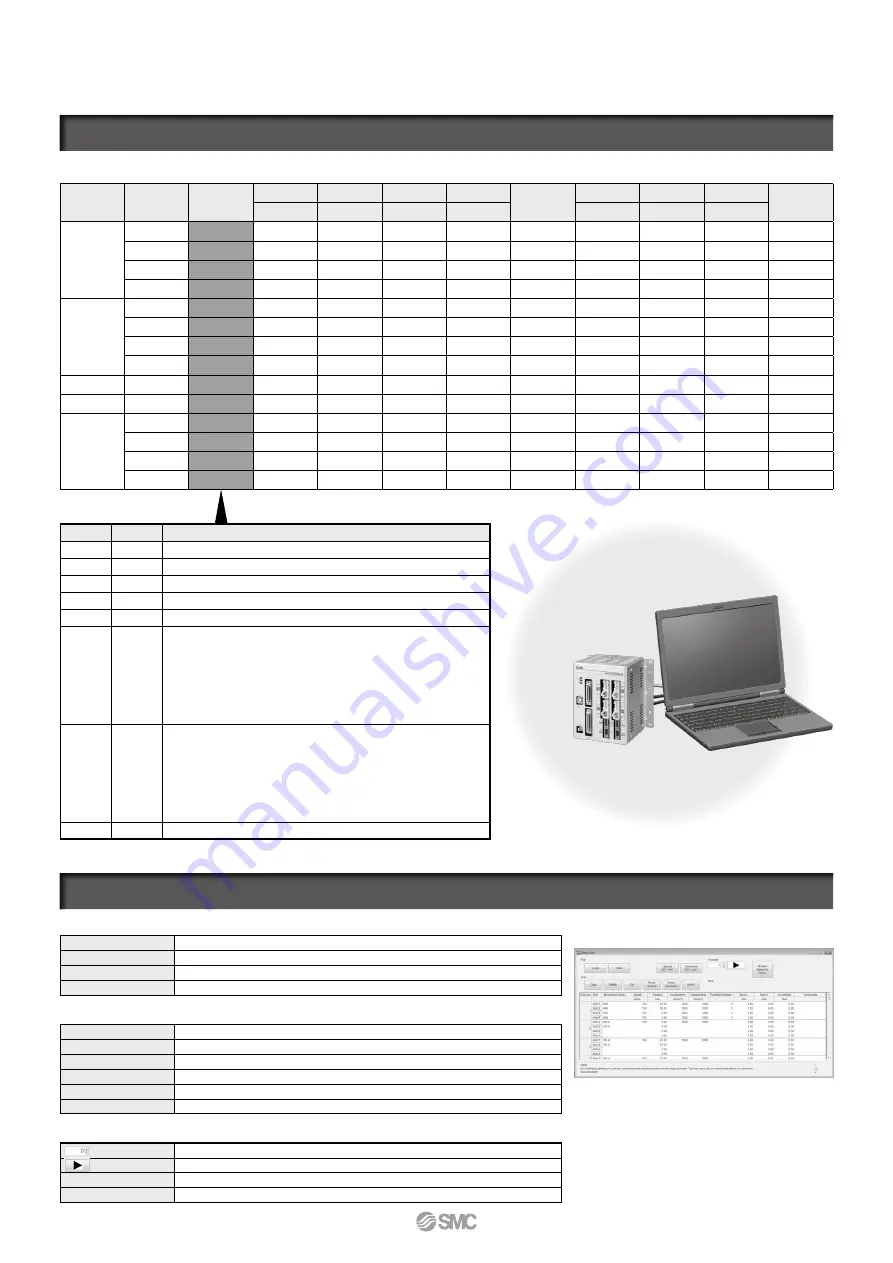
Easy file management

Load

The step data is loaded from the file.

Save

The step data is saved in a file.

Upload

The step data is loaded from the controller.

Download

The step data is written in the controller.

Abundant edit functions

Copy

The selected step data is copied to the clipboard.

Delete

The selected step data is deleted.

Cut

The selected step data is cut.

Paste (Insert)

The step data copied to the clipboard is inserted into the cursor’s position.

Paste (Overwrite)

The step data copied to the clipboard overwrites the data at the cursor position.

Insert

A blank line is inserted in the selected step data line.

Operation confirmation of entered step data

Enter the step number to be executed.
Executes the specified step number.

Stop

Displays whether the step number is being executed or stopped.

All axes return to origin Performs a return to origin of all the valid axes.

Step data window

Movement mode Pushing operation

Details

Blank

Invalid data (Invalid process)

ABS

v

Moves to the absolute coordinate position based on the origin of the actuator.

INC

v

Moves to the relative coordinate position based on the current position.

LIN-A

Moves to the absolute coordinate position based on the origin of the actuator by linear interpolation.

LIN-I

Moves to the relative coordinate position based on the current position by linear interpolation.

CIR-R


1

Axis 1 is assigned to the X-axis and Axis 2 to the Y-axis, and moves 

in the clockwise direction by circular interpolation. Specifies the 

target coordinates and center coordinates by the relative coordinates 

from the current position. The position data is assigned as follows.

Axis 1: Target position X

Axis 2: Target position Y

Axis 3: Center point X

Axis 4: Center point Y

CIR-L


1

Axis 1 is assigned to the X-axis and Axis 2 to the Y-axis, and moves in 

the counter-clockwise direction by circular interpolation. Specifies the 

target coordinates and center coordinates by the relative coordinates 

from the current position. The position data is assigned as follows.

Axis 1: Target position X

Axis 2: Target position Y

Axis 3: Center point X

Axis 4: Center point Y

SYN-I

Moves to the relative coordinate position based on the current position by synchronous control.

1: Performs a circular operation on a plane using Axis 1 and Axis 2.

4 axis operation can be set collectively in one step.

Step Data Input: Max. 

2048 

points

Step Data Input: Max. 

2048 

points

1

JXC73/83/93

 Series

Содержание JXC73 Series

Страница 1: ...Step Motor Controller Parallel I O Type Positioning pushing operation Step data input Max 2048 points Space saving reduced wiring 4 axis synchronous control Absolute relative position coordinates ins...

Страница 2: ...Executes the specified step number Stop Displays whether the step number is being executed or stopped All axes return to origin Performs a return to origin of all the valid axes Step data window Move...

Страница 3: ...ENC To MOT To CI To C PWR PLC VI O cable Option Provided by customer Provided by customer VElectric actuators 1 VMotor control power supply connector Accessory Applicable cable size AWG20 0 5 mm2 VMo...

Страница 4: ...et cable Category 5 or higher Provided by customer Provided by customer VElectric actuators 1 V Motor control power supply connector Accessory VMotor power supply connector Accessory VCable with main...

Страница 5: ...n Actuators should be ordered separately For the Speed Work Load graph of the actuator refer to the LECPA section in the Model Selection page of the WEB catalog of electric actuators 4 axis type 4 axi...

Страница 6: ...er supply with inrush current protection for the motor drive power and motor control power supply 2 Power consumption depends on the actuator connected Refer to the actuator specifications for further...

Страница 7: ...the dimension drawings above for the mounting dimensions L Dimension JXC Z1 with 6 mounting screws This should be used when the DIN rail mounting bracket is mounted onto a screw mounting type control...

Страница 8: ...nsion drawings above for the mounting dimensions L Dimension JXC Z1 with 6 mounting screws This should be used when the DIN rail mounting bracket is mounted onto a screw mounting type controller after...

Страница 9: ...4 lock release 0 M PWRcv Motor power supply connector 1 For Axis 3 4 Motor power supply Common 1 P1 P2 EtherNet IPTM communication connector Connect Ethernet cable 1 Connectors are included Refer to...

Страница 10: ...erminal LKRLS terminal are common M 24V Motor power supply Power supply supplied to the motor power Manufactured by PHOENIX CONTACT Part no MSTB2 5 2 STF 5 08 Terminal name Function Details C 24V Moto...

Страница 11: ...18 White Black 4 23 White Red 1 28 White Red 2 33 White Red 3 38 White Red 4 4 Yellow Black 1 9 Yellow Black 2 14 Yellow Black 3 19 Yellow Black 4 24 Yellow Red 1 29 Yellow Red 2 34 Yellow Red 3 39 Ye...

Страница 12: ...ing changes depending on the type of the parallel I O NPN or PNP Output Signal Name Details OUT0 to OUT8 Outputs the step data no during operation BUSY OUT9 Outputs when the operation of the actuator...

Страница 13: ...ame Details BUSY1 Busy signal for axis 1 BUSY2 Busy signal for axis 2 BUSY3 Busy signal for axis 3 BUSY4 Busy signal for axis 4 AREA1 Area signal for axis 1 AREA2 Area signal for axis 2 AREA3 Area sig...

Страница 14: ...ece while the actuator is moving An injury can result 7 Do not connect the power supply or power up the product until it is confirmed that the workpiece can be moved safely within the area that can be...

Страница 15: ...Safety Instructions Be sure to read the Handling Precautions for SMC Products M E03 3 and Operation Manual before use...

Отзывы: