background image

10

SmartSolar™ 

Installation Instructions & Owners’ Manual

Sliding Gate Opener Set Up

ESV-24 EasySlider

®

 & ESV-24MS EasySlider

®

09

Fig

PLEASE NOTE: 

CB-11 fi rmware must be v0.65 or 

higher for SmartSolar™ compatibility

WARNING: 

Do not connect the batteries until 

Step B5 is completed.

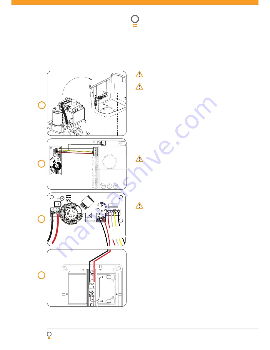
Step B4 - Mount the Charger Board

Unplug the drive unit from mains power.
Remove the main cover, then remove the 
transformer, EMC board (if fi tted) and mains power 
cable.
Mount the Charger Board inside the cover using 
four (4) M4x8 screws (Fig. 09).
Plug the Charger Board’s three wire harness (red/
yellow/black) into the CB-11 board’s “SBY-3” 
connector (Fig. 10).
Plug the Charger Board’s one wire harness (white) 
into the “24vac in” connector on CB-19 control 
board (Fig. 10).

IMPORTANT WARNING: 

Do not connect battery 

or solar panel polarity incorrectly - this will result 

in serious damage to components.

Step B5 - Connect the Solar Panel

Feed the Solar Panel’s cable through black grommet 
which the mains power cord ran through
Connect the 

red wire

 to the Charger Board’s 

SOLAR+

” connector, and the 

black wire 

to the 

–SOLAR

” connector (Fig. 11).

WARNING: 

During Step B6 the opener will 

become active. 

Step B6 - Mount & Connect the Battery

Mount the Battery Box close to the opener.
Feed the 2-core 18awg gauge cable (supplied) 
through the Battery Box’s grommet.
Connect the 

red wire

 to the Battery Box’s “

+

” 

terminal, and the 

black wire 

to the “

” terminal 

(Fig. 12).
Feed the other end of the battery cable through the 
drive unit’s black  grommet.
Connect the 

red wire

 to the Charger Board’s 

BAT+

” connector, and the 

black wire 

to the “

BAT

” connector (Fig. 11).

Step B7 - Re-setup and Test the Opener

Select Menu 7 on the control board, press “SET”, 
select Sub Menu 7 (“Battery/Solar”) and enable 
using the “OPEN” and CLOSE” buttons.
Setup travel limits and transmitters as per the slider  
instruction manual.
Press either “OPEN” or “CLOSE” buttons, or use a 
transmitter to operate the gate.
Refi t the Control Box’s cover. 

1.
2.

3.

4.

5.

1.

2.

1.
2.

3.

4.

5.

1.

2.

3.

4.

10

Fig

11

Fig

Re

d Wi

re

Black

Wi

re

12

Fig


 B

la

ck

 F

ro

m


 R

e

d

 F

ro

m


To 

control

Board

Содержание SmartSolar

Страница 1: ...PN 13208 Manual v1 02 Solar Power Kits For Automatic Technology Openers INSTALLATION INSTRUCTIONS OWNERS COPY SmartSolar SmartPlanetTM Solutions...

Страница 2: ...t such may be lawfully excluded hereby expressly disclaims all conditions or warranties statutory or otherwise which may be implied by laws as conditions or warranties of purchase of an Automatic Tech...

Страница 3: ...Charger Board Layout 6 Installing the Solar Panel 8 Swing Gate Opener Set Up 9 Sliding Gate Opener Set Up 10 Overhead Door Opener Set Up 11 Roll Up Door Opener Set Up GDO 6 EasyRoller 12 Roll Up Door...

Страница 4: ...er or spray directly with a hose or other device Install the solar charger kit in a location where it is out of reach of children The solar charger kit contains sealed lead acid batteries that must be...

Страница 5: ...to prevent reverse current The charger module will not overcharge the batteries and to extend the life of batteries the unit will shut down if the batteries voltage drops below 19V Batteries are char...

Страница 6: ...nnector BAT connects the from the battery box to the charger board Connect the red wire from battery box to the connector Red wire from solar harness connects to this terminal input White wire White w...

Страница 7: ...Charger Board Setup J4 Connector 20watt jumper this jumper has to be on both pins of j4 connector for 20watt solar panel and must be removed for 30 watt solar panel J5 Connector 30watt jumper this jum...

Страница 8: ...ned by the following equation Fig 05 L 15 Where is panel s tilt angle from the horizontal and L is the latitude of the mounting location See Fig 04 for a list of pre calculated panel angles for major...

Страница 9: ...Control Box s grommet Connect the red wire to the Charger Board s SOLAR connector and the black wire to the SOLAR connector Fig 07 WARNING During Step A6 the opener will become active Step A6 Mount Co...

Страница 10: ...h black grommet which the mains power cord ran through Connect the red wire to the Charger Board s SOLAR connector and the black wire to the SOLAR connector Fig 11 WARNING During Step B6 the opener wi...

Страница 11: ...l result in serious damage to components Step C5 Connect the Solar Panel Feed the Solar Panel s cable through black grommet located on the top of the plastic drive unit cover Connect the red wire to t...

Страница 12: ...eed the Solar Panel s cable through black grommet on the chassis Connect the red wire to the Charger Board s SOLAR connector and the black wire to the SOLAR connector Fig 19 WARNING During Step D6 the...

Страница 13: ...rd or battery terminals IMPORTANT WARNING Do not connect battery or solar panel polarity incorrectly this will result in serious damage to components WARNING During Step E6 the opener will become acti...

Страница 14: ...consumption current per day Without P E Beams 2 75 3Ah 3 7Ah 3 4 4 4Ah With P E Beams 4 66 4 8Ah 5 55Ah 5 31 6 3Ah With 2 x P E Beams 7 23 8 23Ah Average total consumption current per hour Without P E...

Страница 15: ...ain the equipment in a proper working order as per clauses d through i installation adjustment or use which is not in accordance with the instructions set out in installation instruction manual attemp...

Страница 16: ...om au www ata aust com au December 2008 Automatic Technology Australia Pty Ltd All rights reserved SecuraCode EasyRoller EasySlider SecuraLift SecureSwing SecureSwing S SmartSolar SmartPlanet and Elit...

Отзывы: