HGM501 Gen-set Controller
USER MANUAL
Smartgen Technology
Страница 1: ...HGM501 Gen set Controller USER MANUAL Smartgen Technology...
Страница 2: ...ronic means or other without the written permission of the copyright holder Smartgen Technology reserves the right to change the contents of this document without prior notice Version History Date Ver...
Страница 3: ...NICAL DATA 5 4 OPERATION 6 4 1 BUTTON DESCRIPTION 6 4 2 START STOP OPERATION 7 4 2 1 STARTING PROCEDURE 7 4 2 2 STOPPING PROCEDURE 7 5 AUTO PROTECTION 8 6 TERMINAL 9 7 CONFIGURABLE PARAMETERS 10 7 1 C...
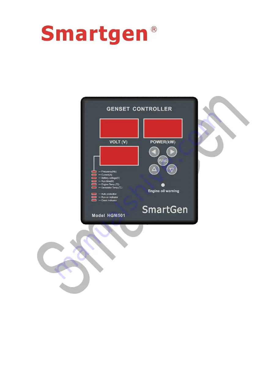
Страница 4: ...RISTICS 1 Two specialized LED displays single phase voltage display and total active power voltage display calculated using single phase power taking load as balanced 2 Multifunction LED display that...
Страница 5: ...ase 4 wire L and N only AC 30V 360V ph N AC 30V 360V ph N AC 30V 360V ph N Alternator frequency 50 60Hz Start relay output 7A DC12V power supply output Fuel relay output 7A DC12V power supply output C...
Страница 6: ...alarm UP SCROLL 1 During parameter configuration pressing this button increases the set value 2 During normal operation press this button to switch to the upper LED DOWN SCROLL 1 During parameter conf...
Страница 7: ...6 Generator temp 7 Auto protection If on auto protection is enabled if not it is disabled 8 Run on indicator Fuel relay output indicator 9 Crank indicator Start output indicator 10 Engine oil warning...
Страница 8: ...g If the set value is exceeded by 5 7 5 and continuous for more than 3 hours then alarm shutdown will be initiated If the set value is exceeded by 7 5 10 and continues for more than 1 hours alarm shut...
Страница 9: ...after Safety On Delay when voltage frequency overload high temperature protection is initiated fuel output deactivates 6 TERMINAL HGM501 controller back panel is shown below Terminal connections desc...
Страница 10: ...lock START input 1 5mm2 Hand turn start start relay output Output activates when electric lock key is turned to START position 11 Start relay output 1 5mm2 Rated current 7A power supplied by terminal...
Страница 11: ...4 Select this according to the used sensor 7 2 PARAMETER CONFIGURATION Before using controller for the first time parameters must be configured rated voltage rated frequency rated power set values mus...
Страница 12: ...nd auto protection will continue to be enabled use or to make indicator off and press to disable auto protection When the light indicator is off it means that auto protection is disabled Enabling this...
Страница 13: ...sure all parameters are configured correctly and oil pressure light is on 3 Ensure the controller DC power supply is fused and correctly connected to the positive and negative of starter battery 4 Tak...
Страница 14: ...oller is designed for panel mounting it is held with the help of fixing clips Overall and cutout dimensions can be seen below unit mm 1 Battery Voltage Input NOTE HGM501 controller is suitable for 9 1...
Страница 15: ...n generator is on load C T secondary must not be open circuit 2 Withstanding voltage test CAUTION If withstanding voltage test is conducted after the controller has already been installed onto the con...