HAT700 SERIES
HAT700/HAT700I/HAT700B/HAT700BI/HAT700S
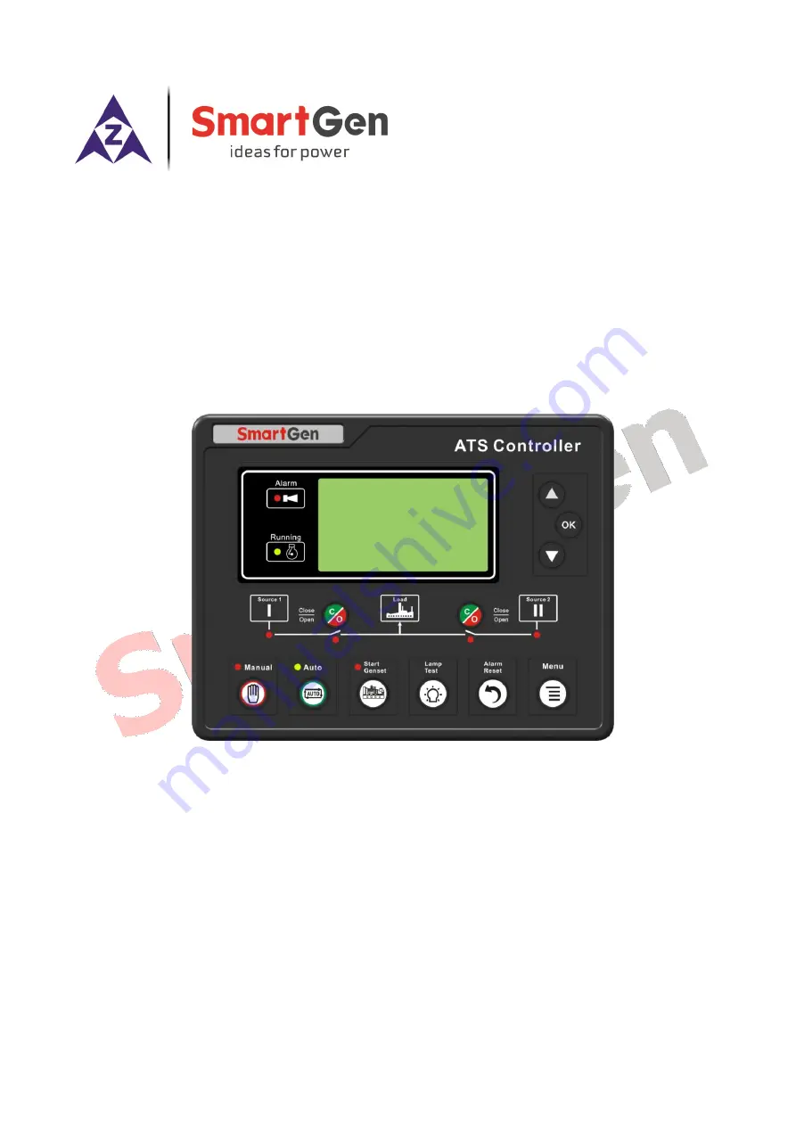
ATS CONTROLLER
USER MANUAL
SMARTGEN (ZHENGZHOU) TECHNOLOGY CO., LTD.
Страница 1: ...HAT700 SERIES HAT700 HAT700I HAT700B HAT700BI HAT700S ATS CONTROLLER USER MANUAL SMARTGEN ZHENGZHOU TECHNOLOGY CO LTD...
Страница 2: ...ns for the copyright holder s written permission to reproduce any part of this publication should be addressed to SmartGen Technology at the address above Any reference to trademarked product names us...
Страница 3: ...5 WARN ALARMS 14 7 2 6 FAULT ALARMS 15 7 2 7 INDICATION 15 7 2 8 OTHERS 16 7 3 MAIN MENU 16 8 START STOP OPERATION 17 8 1 MANUAL START STOP 17 8 1 1 PANEL START STOP 17 8 1 2 REMOTE START STOP 17 8 2...
Страница 4: ...0 Series ATS Controller 2018 12 13 Version 1 5 Page 4 of 51 12 ATS POWER SUPPLY 39 13 LOAD SHEDDING 40 14 COMMUNICATION CONFIGURATION 41 15 DESCRIPTION OF CONNECTING TERMINALS 41 16 TYPICAL WIRING DIA...
Страница 5: ...oltage over under frequency loss of phase and other abnormal condition occurs This controller has full consideration in various application of ATS automatic transfer system and can be directly used fo...
Страница 6: ...eters can be set on site Passwords authentication ensures authorized staff operation only 15 The genset can be Manual Test on site to achieve start stop operation 16 ATS Controller has function of aut...
Страница 7: ...Rated Frequency 50 60Hz Close Relay Output 16A AC250V Volts free output Auxiliary Relay Output 16A 7A AC250V Volts free output Digital Input GND B connect is active Communication RS485 isolated interf...
Страница 8: ...hase Reactive Power kvar Q1 Q2 Q3 Load 3 Phase Total Reactive Power kvar Q1 Q2 Q3 Load 3 Phase Apparent Power kVA A1 A2 A3 Load Total Apparent Power kVA A1 A2 A3 Load 3 Phase Power Factor PF PF1 PF2 P...
Страница 9: ...ower Normal It is light on when S1 is normal flashing when S1 is abnormal 1time per sec off when there is no S1 power S1 Close Status It is light on when S1 close input is activated S2 Power Normal It...
Страница 10: ...y During the S2 is waiting to synchronizing pressing this key will de energize the S2 sync closing relay Manual Mode Set controller as Manual mode Auto Mode Set controller as Auto mode Test Run Press...
Страница 11: ...Current Mode Alarm Status Indications Others Load I 500 500 500A Phase 0 120 240 TkW 329 PF 1 00 Tkvar 1 3 TkVa 330 Auto Mode 3 phase current 3 phase current phase Total active power power factor Tota...
Страница 12: ...uto Mode S1 Total Close Times S2 Total Close Times Current Mode Alarm Status Indications Others Alarms Alarms 1 2 Warn Alarm S1 Over Current Fault Alarm S1 Failed to Closed Alarm number and account Al...
Страница 13: ...ge is 0 5 S2 Over Volt Voltage is higher than the set value 6 S2 Under Volt Voltage has fallen below the set value 7 S2 Over Freq Frequency is higher than the set value 8 S2 Under Freq Frequency has f...
Страница 14: ...ctive when the sync requirements are satisfied 14 Waiting S1 PF Before S1 is closed it s the delay time to confirm S1 PF Input signal is active 15 Waiting S2 PF Before S2 is closed it s the delay time...
Страница 15: ...ault it will initiate a fault alarm 8 S1 Genset Fault If there is S1 fail to start failure occurs when S1 Gens S2 Gens system is selected it will initiate a fault alarm 9 S2 Genset Fault If there is S...
Страница 16: ...alance Gen Hours Mode Balance Run Start Mode is active when S1 Gens S2 Gens system is active 12 Master Slave Gen Start Mode Master Run Start Mode is active when S1 Gens S2 Gens system is active 13 Aut...
Страница 17: ...nnect the S1 start signal i e stop the running S1 genset S1 Genset Start Output the S1 start signal i e start the S1 genset S2 Genset Stop Disconnect the S2 start signal i e stop the running S2 genset...
Страница 18: ...n process if Auto Mode is selected the current status will be hold and the cycle run countdown will be suspended Master Run Mater genset will be start when remote start signal is active During the sta...
Страница 19: ...tart monthly weekly and daily Run Monthly Monthly start date and time can be set Run Weekly Can start the genset at the same time in couple days of a week Eg Start the genset at 8 00 a m from Monday t...
Страница 20: ...available Delay 0 3600 s 5 The delay from S2 voltage normal to abnormal 5 Master Slave Set 0 2 0 0 S1 Master 1 S2 Master 2 No Master 6 System Type Set 0 3 0 0 S1 Mains S2 Gen 1 S1 Gen S2 Mains 2 S1 Ma...
Страница 21: ...Sequence Wrong 0 1 1 0 Disable 1 Enable SWITCH SETTING 1 Definite C O Time 0 1 0 0 Disable 1 Enable Disable The output time was judged depends on the close relay the longest output time up to the set...
Страница 22: ...larm will be removed after the synchronization is successful or exit When the Fault Alarm is selected the alarm will be removed only when the Reset button is pressed 16 Transfer in Sync Fail 0 1 0 0 D...
Страница 23: ...r Volts alarm will be initiated if the battery voltage has fallen below the set value 10 Battery Under Volt Return Value 0 100 0 V 10 5 Battery Under Volts alarm will be removed if the battery voltage...
Страница 24: ...e 0 1 1 0 Disable 1 Enable 2 CT Primary 5 5 6000 A 500 The primary current of CT 3 S1 Full Load Rating 5 6000 A 500 The current of S1 taking full load 4 S2 Full Load Rating 5 6000 A 500 The current of...
Страница 25: ...ed Open 2 Active Type 0 1 0 0 Closed to active 1 Open to active 3 Digital Input 2 0 29 8 Switch Trip Input 4 Active Type 0 1 0 0 Closed to active 1 Open to active 5 Digital Input 3 0 29 0 Not Used 6 A...
Страница 26: ...ntents Setting 0 92 0 Not Used 23 Combined 2 And Out Active Type 0 1 0 0 Normally open 1 Normally close 24 Combined 2 And Out Contents Setting 0 92 0 Not Used 25 Combined 3 Or Out 1 Active Type 0 1 0...
Страница 27: ...pe 0 1 0 0 Normally open 1 Normally close 44 Combined 6 Or Out 1 Contents Setting 0 92 0 Not Used 45 Combined 6 Or Out 2 Active Type 0 1 0 0 Normally open 1 Normally close 46 Combined 6 Or Out 2 Conte...
Страница 28: ...al will deactivated 8 Breaker Trip Input Trip failure input 9 S1 Close Inhibit In Manual mode S1 manual close is inhibited if breaker already closed users should open it manually In Auto mode if break...
Страница 29: ...arm It includes Transition Fault alarm and Over Current alarm 13 Common Warn Alarm It includes S1 Phase Sequence Wrong alarm S2 Phase Sequence Wrong alarm Over Current and Forced Open alarm 14 Transit...
Страница 30: ...Open Control Control the S2 switch to open 38 Reserved 39 Reserved 40 NEL1 Trip Control the NEL off load when the output is active It can control the NEL on load again when the output deactivated 41 N...
Страница 31: ...f Phase 79 S2 Phase Seq Wrong 80 Reserved 81 Reserved 82 Sync Fail Output when the synchronization is failed 83 Sync Waiting Output when the genset is waiting for synchronization 84 Switching Output d...
Страница 32: ...f probably condition output SW1 output port 1 is active Close when probably condition output SW1 is active inactive close when active disconnect when inactive Contents of probably condition output SW2...
Страница 33: ...te time delay Different overcurrent value has corresponding delay Inverse Definite Minimum Time IDMT overcurrent delay decrease with the increase of overcurrent Different overcurrent value has corresp...
Страница 34: ...status S2 Power supply status Date and time Press to view the detailed record information press it again to exit the current record Action Event 10 99 S1 Genset Start U1LN 0 0 0V U2LN 220 221 219V F1...
Страница 35: ...d 6 NEL1 Trip Record when the NEL 1 Trip output 7 NEL2 Trip Record when the NEL 2 Trip output 8 NEL3 Trip Record when the NEL 3 Trip output 9 Genset Start Record when the Genset Start signal output 10...
Страница 36: ...her power after the synchronization requirements have reached Sync Closing If Sync Closing is enabled its function will active otherwise Sync Closing function will Not be implemented Volt Difference I...
Страница 37: ...en relay will deactivated During the synchronization process if Close or Open action is not successful after the Sync Transfer Time has expired Fail to Close or Fail to Open alarm will be initiated S1...
Страница 38: ...chronization is not successful after the Waiting Sync delay has expired Fail to Sync alarm will be initiated while Sync Waiting signal will output continuously until the synchronization is successful...
Страница 39: ...e to normally close Pin5 and normally open Pin7 contact of auxiliary output 1 connect N phase of S1 and S2 to normally close Pin8 and normally open Pin10 contact of auxiliary output 2 And then connect...
Страница 40: ...If NEL manual trip input is active earthed failing edge is active NEL1 will trip without delay If NEL manual trip input is active again NEL2 will trip If NEL manual trip input is active the third time...
Страница 41: ...mmunication Protocol please refer to HAT600 Communication Protocol Communication parameters Module address 1 range 1 254 User can set it Baud rate 9600 bps 2400 4800 9600 19200bps Data bit 8bit Parity...
Страница 42: ...ux Input 1 User defined Ground connected is active 24 Aux Input 2 Ground connected is active 25 Aux Input 3 Ground connected is active 26 Aux Input 4 Ground connected is active 27 Aux Output 3 Volts f...
Страница 43: ...ATS Controller 2018 12 13 Version 1 5 Page 43 of 51 16 TYPICAL WIRING DIAGRAM ATYS3 Wiring Diagram Parameters Setting Switch Type PC Three stage Aux Output 1 ATS Power L Aux Output 2 ATS Power N Aux...
Страница 44: ...R USER MANUAL HAT700 Series ATS Controller 2018 12 13 Version 1 5 Page 44 of 51 SGQ N T Wiring Diagram Parameters Setting Switch Type PC Two stage Aux Output 1 ATS Power L Aux Output 2 ATS Power N Aux...
Страница 45: ...ER USER MANUAL HAT700 Series ATS Controller 2018 12 13 Version 1 5 Page 45 of 51 SGQ M Wiring Diagram Parameters Setting Switch Type PC Two stage Aux Output 1 ATS Power L Aux Output 2 ATS Power N Aux...
Страница 46: ...TS Controller 2018 12 13 Version 1 5 Page 46 of 51 VITZRO PHETENG Wiring Diagram Parameters Setting Switch Type CB CC Aux Output 1 ATS Power L Aux Output 2 ATS Power N Aux Output 4 S1 Open Control Aux...
Страница 47: ...ATS CONTROLLER USER MANUAL HAT700 Series ATS Controller 2018 12 13 Version 1 5 Page 47 of 51 Contactor Wiring Diagram Parameters Setting Switch Type CB CC Aux Output 6 Gen Start Output Close Continuo...
Страница 48: ...AT700 Series ATS Controller 2018 12 13 Version 1 5 Page 48 of 51 ATYSM3S Wiring Diagram Parameters Setting Switch Type PC Three stage Aux Output 1 ATS Power L Aux Output 2 ATS Power N Aux Output 4 S1...
Страница 49: ...ller 2018 12 13 Version 1 5 Page 49 of 51 Breaker Wiring Diagram MCH Stored Energy Motor MN Under Voltage Trip MX Open Relay XF Close Relay Parameters Setting Switch Type CB CC Aux Output 4 S1 Open Co...
Страница 50: ...tart Output NOTE All above are application diagrams of HAT700 series ATS controllers However HAT700 and HAT700B have no sample current input please skip over the current part of the diagram Note Auxil...
Страница 51: ...sistor between RS485 A terminal and B terminal is recommended Auxiliary Output Error Check auxiliary output connections pay attention to normally open contact and normally close contact Check the outp...