background image

FCC COMPLIANCE STATEMENT

FCC INFORMATION :


THIS EQUIPMENT HAS BEEN TESTED AND FOUND TO COMPLY WITH 

THE LIMITS FOR A CLASS A DIGITAL DEVICE, PURSUANT TO PART 15 OF THE FCC RULES. 

THESE LIMITS ARE DESIGNED TO PROVIDE REASONABLE PROTECTION AGAINST HARMFUL 

INTERFERENCE WHEN THE EQUIPMENT IS OPERATED IN A COMMERCIAL ENVIRONMENT. 

THIS EQUIPMENT GENERATES, USES, AND CAN RADIATE RADIO FREQUENCY ENERGY AND IF 

NOT INSTALLED AND USED IN ACCORDANCE WITH THE INSTRUCTION MANUAL, MAY CAUSE 

HARMFUL INTERFERENCE TO RADIO   COMMUNICATIONS. OPERATION OF THIS EQUIPMENT 

IN A RESIDENTIAL AREA IS LIKELY TO CAUSE HARMFUL INTERFERENCE IN WHICH CASE THE 

USER WILL BE REQUIRED TO CORRECT THE INTERFERENCE AT HIS OWN EXPENSE

.

CAUTION :


CHANGES OR MODIFICATIONS NOT EXPRESSLY APPROVED BY THE PARTY 

RESPONSIBLE FOR COMPLIANCE COULD VOID THE USER'S AUTHORITY TO OPERATE THE 

EQUIPMENT.

THIS CLASS A DIGITAL APPARATUS COMPLIES WITH CANADIAN ICES-003.

CET APPAREIL NUMERIQUE DE LA CLASSE A EST CONFORME A LA NORME NMB-003 DU 
CANADA.

WARNING

This is a Class A product.  In a domestic environment this product may cause radio interference in 

which case the user may be required to take adequate measures.

CE COMPLIANCE STATEMENT

4

Содержание STM-200

Страница 1: ...www smartec security eu Smartec STM 200 LCD Monitor User Manual ...

Страница 2: ...ECTS HOWEVER WE CANNOT ASSUME RESPONSIBILITY FOR ANY CONSEQUENCES RESULTING FROM THE USE THEREOF THE INFORMATION CONTAINED HEREIN IS SUBJECT TO CHANGE WITHOUT NOTICE REVISIONS OR NEW EDITIONS TO THIS PUBLICATION MAY BE ISSUED TO INCORPORATE SUCH CHANGES LIMITATION OF LIABILITY ...

Страница 3: ...ng to be used for several days or more To disconnect the cord pull it out by the plug Never pull the cord itself Allow adequate air circulation to prevent internal heat build up Do not place the unit on surfaces rugs blankets etc or near materials curtains draperies that may block the ventilation holes Height and vertical linearity controls located at the rear panel are for special adjustments by ...

Страница 4: ...CE TO RADIO COMMUNICATIONS OPERATION OF THIS EQUIPMENT IN A RESIDENTIAL AREAIS LIKELY TO CAUSE HARMFUL INTERFERENCE IN WHICH CASE THE USER WILL BE REQUIRED TO CORRECT THE INTERFERENCE AT HIS OWN EXPENSE CAUTION CHANGES OR MODIFICATIONS NOT EXPRESSLY APPROVED BY THE PARTY RESPONSIBLE FOR COMPLIANCE COULD VOID THE USER S AUTHORITY TO OPERATE THE EQUIPMENT THIS CLASS A DIGITAL APPARATUS COMPLIES WITH...

Страница 5: ...e plug a plug having a third grounding pin This plug will only fit into a grounding type power outlet This is a safety feature If you are unable to insert the plug into the outlet contact your electrician to replace your obsolete outlet Do not defeat the safety purpose of the grounding type plug POWER CORDS Protect the power cord from being walked on or pinched particularly at plugs convenience re...

Страница 6: ...ER 3 REMOTE CONTROL 10 CHAPTER 4 SETUP MODE 11 OVERVIEW 11 OSD WINDOW OF MAIN MENU 11 SELECTING SCREEN MODE 12 MOTION SETUP 13 TIME DATE 14 PICTURE ADJUSTMENT 15 CAMERA TITLE 16 CAMERA ADJUSTMENT 17 PIP ADJUSTMENT 18 CONFIGURATION 18 ADJUSTING OSD WINDOW 20 CHAPTER 5 TROUBLESHOOTING 21 CHAPTER 6 SPECIFICATIONS 22 TABLE OF CONTENTS 6 ...

Страница 7: ...owing the monitor image to switch to one or both of the camera images which contains motion The monitor provides five display modes including full screen CAM1 or CAM2 picture in picture PIP mode and picture by picture PBP mode All monitor programming is accomplished via an IR remote control High Brightness and Contrast Color TFT LCD Monitor High Resolution Display Motion Detection Capability PIP P...

Страница 8: ...CHAPTER 2 FRONT AND REAR PANEL THE FRONT PANEL A IR LIGHT SENSOR Remote control sensor Light sensor for detecting ambient light A 8 ...

Страница 9: ... 12V OUT C Video input connectors of the CA1 Camera 1 and the CA2 Camera 2 video sources Use the BNC connections CA1 CA2 IN D Video output connectors of the CA1 Camera 1 and the CA2 Camera 2 CA1 CA2 OUT E The video output connector The same video as the picture displayed MAIN G Audio Input connector AUDIO CA1 OUT CA2 OUT AUDIO R L MAIN DC 12V IN DC 12V OUT A B C D E F CA1 IN CA2 IN 9 ...

Страница 10: ... 10 Power Turns the monitor on or off 11 Numbers 0 9 1 3 CA1 3 Displays the selected camera in full on the screen 4 9 0 Not available 12 Freeze Not available 13 Capture Not available 14 Menu Turns the OSD menu on off 15 Sequence Sequences the picture from CA1 to CA3 16 History Not available 1 4 7 2 5 8 0 3 6 9 FREEZE CA1 CA4 CA2 CA3 CAPTURE SEQUENCE VCR QUAD REPLAY PB PC HISTORY S VIDEO COMPONENT ...

Страница 11: ... are saved when exiting the OSD menu MAIN MENU This monitor has 9 main OSD items Press the MENU button to turn the main OSD Menu on or off The MENU button is also used to go to the previous OSD menu Use UP DOWN button to move up down in the OSD menu Use LEFT or RIGHT button to display the sub menu of the item where the horizontal indication bar is located or decrease or increase the amount of the ...

Страница 12: ...PIP window CA1 will be the main window CA1 Main PIP The PIP window appears if motion occurs on the PIP camera and then disappears after DWELL TIME expires The DWELL TIME is set the MOTION SET menu CA1 CA1 CA1 CA2 CA2 ITEMS DESCRIPTIONS MODE 1 MODE 2 MODE 3 MODE 4 PBP display Half of the horizontal area is cropped on each camera The screen switches to full display when motion occurs within the file...

Страница 13: ...on is processed When it is set to 5 SEC the motion detection is processed at every five seconds This means that the minimum switching interval from the camera to the other camera is 5 seconds when this monitor is operated in MODE 1 It supports up to 99 seconds DWELL TIME If there is a motion in the field of view of the CA2 the main screen switches to the CA2 image for a length of time set in the D...

Страница 14: ... on the time and date setup screen is date format This is used to select between the following three date formats FORMAT US default EURO ASIA DISPLAY MM DD YYYY DD MM YYY YYYY MM DD EXAMPLE 01 01 2004 01 01 2004 2004 01 01 DATE This field is used to set the current date The format displayed on the screen is dependent on the format option TIME This field is used to set the time in the 24 hour forma...

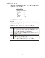
Страница 15: ...e and date on the screen 9 Press MENU to go to the previous OSD window or exit from the OSD PICTURE ADJUSTMENT PICTURE OVERVIEW The PICTURE menu allows you to modify the picture quality by adjusting the contrast brightness color tint and sharpness VOLUME 00 CONTRAST 19 BRIGHTNESS 19 COLOR 50 1 TINT 50 SHARPNESS 06 MOTION ADJUST 2 1 Tint is only activated in NTSC system VOLUME The volume adjustment...

Страница 16: ... screen when the display option is ON and the camera is selected The default camera title is CA with the corresponding number Following are the available characters for camera titles regardless of the language setting DISPLAY To display the camera title on the screen select the DISPLAY option ON Use the following steps to adjust the CAMERA TITLE option STEP ACTION 1 2 3 Press MENU and then move th...

Страница 17: ...ture sequences in the order of CA1 CA2 CA1 CA2 by pressing the SEQUENCE button on the remote control Use the following steps to set the picture quality of each camera and other options STEP ACTION 1 2 3 Press MENU and then move the horizontal bar to CAMERA ADJUST using or Press or to display sub menu of CAMERA ADJUST Locate the horizontal bar at CAMERA and then select the camera to be adjusted usi...

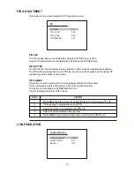
Страница 18: ...xercised not to display PIP window beyond the border of the screen PIP CAMERA This option is used to select which camera is designated as the PIP window If CA1 is designated as the PIP window CA2 will be the Main window This option is only applied on SCREEN MODE 2 3 Use the following steps to set PIP options STEP ACTION 1 2 Press MENU and then move the horizontal bar to PIP option using or Press o...

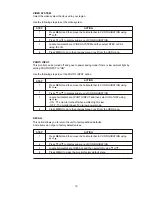
Страница 19: ...TO INPUT option STEP ACTION 1 2 Press MENU and then move the horizontal bar to CONFIGURATION using or Press or to display sub menu of CONFIGURATION 3 Locate horizontal bar at PHOTO INPUT and then select ON of OFF using or ON The monitor turns off when ambient light is low OFF The monitor doesn t go to low power mode 4 Press MENU to go to the previous menu or exit from the OSD menu RECALL This opti...

Страница 20: ... Blending setup menu to change the opaqueness of the background of the OSD Use the following steps to change the BLENDING option STEP ACTION 1 2 3 Press MENU and then move the horizontal bar to OSD MENU using or Press or to display sub menu of OSD MENU Locate the horizontal bar at BLENDING and then choose ON or OFF using or 4 Press MENU to go to the previous menu or exit from the OSD menu TIME Use...

Страница 21: ...rk Adjust the Brightness and Contrast 4 Picture is impropely tinted Check color adjustment 5 Motion not detected or detected too often Adjust sensitivity of motion detection 6 Remote control malfunctions Check the battery terminals Replace the remote control batteries 7 No sound Ensure that the audio cables are firmly connected to both the audio in ports on your monitor Check the volume level CHAP...

Страница 22: ...utput x 2 Main output x 1 1 0Vp p 75 ohm DC 12V 4 9A DC12V 0 5A Max LCD Panel Active Display Area Pixel Format Pixel Pitch Color Depths Contrast Ratio Brightness Viewing Angles L R U D Light Source Lifetime Response Time Camera Video Input Connector Video Mode Video Input Level Video Output Connector Video Output Level Power Requirement Power Consumption DC Output Operating Temperature LCD Video O...

Отзывы: