SDS-1002/3 SETUP GUIDE – STP CABLE/RS232
STEP 3 – CONNECTING THE CAT 5-8 STP CABLE
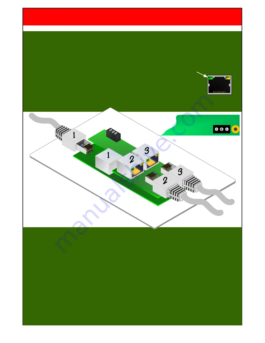
It is important to connect the Cat cables to the correct RJ45s and in the correct sequence. Firstly turn the
plate over so the PCB is on show. If the cables are not numbered then follow this sequence:
1.
Connect each STP cable in turn to RJ45 number 2 until you see the green LED within the RJ45
light indicating correct connection, once found leave the cable connected.
2.
Connect the other STP cables to RJ45 number 1 until its green LED lights,
once found leave the cable connected
3.
Connect the last STP cable to RJ45 number 3 – note that both the LEDs on number 3 do not light
RS232
TX 0V RX
STEP 4 – WIRING FOR RS232
The RS232 port on the rear has a three functions:
1.
Input selection
- as well as the front panel button, RS232 commands can be sent to the wall plate
to select the required input signal type (see protocol document) ideal for integrating into a third
party control system.
2.
Programming control strings
– The SDS-RX1000 unit can store RS232 control strings
associated which each signal type. When a new input is selected the RX1000 will automatically
send the appropriate RS232 command switching the display to the correct format. This facility
provides a complete solution without the need for another control system.
(see programming app).
3.
RS232 pass-through – The SDS units also allow RS232 commands to be passed through the
system and out putted from the SDS-RX1000, ideal for system integration.
SDS-1002 & 1003 SETUP GUIDE
Copyright 2012 Smart-e Ltd
Page 4


