


7 Electrical Connection
SMA Solar Technology AG
Operating manual
SB55-LV-JP-41-BE-en-13
33
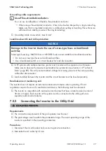
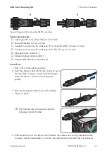
Figure 8: Negative (A) and positive (B) DC connectors
Cable requirements:
☐ Cable type: PV1-F, UL-ZKLA, USE2, H-CV, EM-CE
☐ External diameter: 5.5 mm to 8 mm
☐ Conductor cross-section for cable type PV1-F, UL-ZKLA, USE2: 2.5 mm² to 6 mm²
☐ Conductor cross-section for cable type H-CV, EM-CE: 2 mm² to 6 mm²
☐ Qty single wires: minimum 7
☐ Nominal voltage: minimum 600 V
☐ Using bootlace ferrules is not allowed.
Procedure:
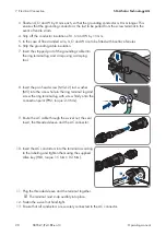
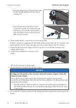
1. Strip 12 mm of the cable insulation.
2. Insert the stripped cable into the DC connector up to
the stop. When doing so, ensure that the stripped
cable and the DC connector are of the same
polarity.
+
3. Press the clamping bracket down until it audibly
snaps into place.
+
☑ The stranded wire can be seen inside the
clamping bracket chamber.
+
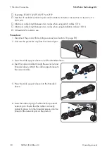
4. If the stranded wire is not visible in the chamber, the cable is not correctly inserted and the
connector must be reassembled. To do this, the cable must be removed from the connector.


