


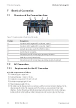


7 Electrical Connection
SMA Solar Technology AG
Operating manual
SB55-LV-JP-41-BE-en-13
28
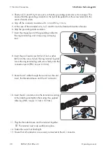
3. Shorten U, O and W by 8 mm each, so that the grounding conductor is 8 mm longer. This
ensures that the grounding conductor is the last to be pulled from the screw terminal in the
event of tensile strain.
4. Strip off the conductor insulation of U, O and W by 15 mm.
5. In the case of fine stranded wire, U, O and W are to be fitted with bootlace ferrules.
6. Strip the grounding cable insulation.
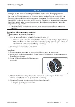
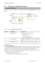
7. Insert the stripped part of the grounding cable into
the ring terminal lug and crimp using a crimping
tool.
8. Insert the pan head screw (M5x12) incl. washer
(M5) into the screw hole in the ring terminal lug and
screw the ring terminal lug with screw firmly onto the
connection point (PH2, torque: 2.5 Nm).
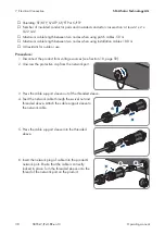
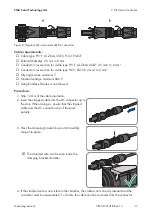
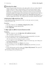
9. Route the AC cable through the swivel nut, the seal
insert, the threaded sleeve and the AC connector.
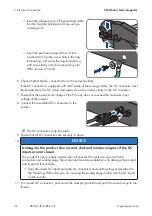
10. Insert the AC conductors into the terminal according
to the labeling and tighten them using the supplied
Allen key (HX3, torque 1.5 Nm ± 0.3 Nm).
W
U
W
U
3x
1
2
11. Plug the threaded sleeve and the terminal together.
☑ The terminal must snap audibly into place.
12. Fasten the swivel nut hand-tight.
13. Ensure that all conductors are securely connected to the AC connector.


