background image

  Maintenance 

SMA America, LLC

84

SB50US-80US-eng-IUS112633

Installation Guide

Setting the Jumper

The Sunny Boy only detects the jumper after it is restarted. All LEDs must go out prior to a restart.

1. Disconnect the Sunny Boy on the AC and DC sides. Wait 5 minutes until the residual voltage 

has been drained.

2. Open the Sunny Boy as described in section 6.2 ”Opening the Sunny Boy” (page 38).
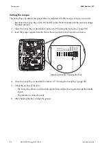
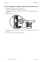
3. Insert the jumper supplied into the slot on the sequential control board shown below.

4. Close the Sunny Boy as described in section 6.7 ”Closing the Sunny Boy” (page 58).
5. Check the air flow of the fans.

– The Sunny Boy draws in cold air through the fans and lets it out again through the handle 

covers. 

– Pay attention to unusual sounds.

6. After checking the fans, remove the jumper.

Jumper position for checking the fans

Содержание SUNNY 6000-US

Страница 1: ...SB50US 80US eng IUS112633 TBUS SB50_60_70US Version 3 3 CA US PV Inverter SUNNY BOY 5000 US 6000 US 7000 US 8000 US Installation Guide...

Страница 2: ...of implied warranties may not apply in all cases under some statutes and thus the above exclusion may not apply Specifications are subject to change without notice Every attempt has been made to make...

Страница 3: ...you must carefully read and follow all instructions cautions and warnings in this manual Warnings in this document A warning describes a hazard to equipment or personnel It calls attention to a proced...

Страница 4: ...en its conductors Arc flashes can occur through air when high voltage current flows Do not work on the product during operation Beware of hot surface The product can become hot during operation Do not...

Страница 5: ...rds applicable in the jurisdiction of installation SMA assumes no responsibility for the compliance or noncompliance with such laws or codes in connection with the installation of the product The prod...

Страница 6: ...livery 17 4 AC Voltage Configuration 18 4 1 Opening the Sunny Boy 18 4 2 Locating Internal Component Parts 19 4 3 AC Voltage Configuration 20 4 4 Jumper for System Configuration 23 5 Mounting 25 5 1 S...

Страница 7: ...6 5 3 DC Wiring without SMA DC Disconnect 50 6 5 4 DC Wiring with SMA DC Disconnect 51 6 5 5 DC Connection with Additional DC Distribution 56 6 6 Communication 57 6 7 Closing the Sunny Boy 58 6 8 Clos...

Страница 8: ...PV String Fuses within the SMA DC Disconnect 86 11 Technical Data 88 11 1 FCC Compliance Information 88 11 2 Sunny Boy Circuit Diagrams 89 11 2 1 Without SMA DC Disconnect 89 11 2 2 With SMA DC Disco...

Страница 9: ...he connected devices is available from the manufacturers of the devices 1 2 Target Group This guide is for qualified personnel Qualified personnel have received training and have demonstrated skills a...

Страница 10: ...electric utility company depending on the interconnection agreement Principle of a PV Plant with a Sunny Boy Anti Islanding Protection A stand alone grid is a status It occurs when the power distribut...

Страница 11: ...performance so as to protect the internal component parts from overheating Interconnection Code Compliance The Sunny Boy has been checked by the certification body and certified according to the guide...

Страница 12: ...er to life due to high voltages in the inverter Risk of death or serious injury due to electric shock Only qualified personnel may perform work on the inverter WARNING During operation the inverter ca...

Страница 13: ...line cross section safety measures and warnings to prevent injuries and or damage to the device and step by step instructions for connecting the Sunny Boy to a PV array to an electric circuit in the h...

Страница 14: ...that delivered the Sunny Boy If it is necessary to send the Sunny Boy back use the original packaging If you require help with a damaged Sunny Boy please contact your SMA dealer or SMA Contact informa...

Страница 15: ...replacement tooth lock washers for connecting the enclosure lid to the Sunny Boy 2 Screws and washers for fastening the Sunny Boy to the wall mounting bracket D 2 Spare jumpers for fan test E 2 Handl...

Страница 16: ...osure lid and the enclosure There may be an ingress of moisture Potential damage to the Sunny Boy Handle the enclosure lid with care Do not lose the screws and conical spring washers of the enclosure...

Страница 17: ...2633 19 4 2 Locating Internal Component Parts Item Description A Sockets for optional communication Piggy Back RS485 or wireless B Display C Status LEDs D Jumpers for configuring the AC voltage and th...

Страница 18: ...the AC voltage select the cable with the correct voltage at the right terminal block C Connect the selected cable to the left side of the left terminal block A 3 Secure all screw terminals If spring...

Страница 19: ...s observe the procedure in 4 4 Jumper for System Configuration page 23 To connect a neutral conductor to the Sunny Boy observe section 6 4 2 AC Connection without SMA DC Disconnect page 41 or section...

Страница 20: ...on SMA America LLC 22 SB50US 80US eng IUS112633 Installation Guide The Sunny Boy 8000 US must not be connected to a 208 V grid When using corner grounded 240 V or 208 V Delta grids Connect terminal L2...

Страница 21: ...possible The following figure provides an overview of the standard settings the settings for grids without neutral conductors and the settings for the fan test The Sunny Boy 8000 US must not be connec...

Страница 22: ...nt of the jumpers for the 240 V Delta system configuration Note the order in which the inverters are connected to the phases Configuration Examples for Jumpers with 240 V Delta 120 V Stinger Configura...

Страница 23: ...tall the inverter in potentially explosive areas WARNING During operation the inverter can become hot Risk of burns Do not touch the enclosure during operation Only touch the lid during operation Inst...

Страница 24: ...stable surface The mounting location must be accessible at all times Mount vertically or tilted backward at max 45 The connection area must point downward Do not install the inverter tilting forward D...

Страница 25: ...away from each other that they are able to draw in sufficient cooling air For sufficient ventilation increase the clearances if required The National Electrical Code may stipulate greater clearances...

Страница 26: ...unting with Wall Mounting Bracket The Sunny Boy is supplied with a T shaped wall mounting bracket that is suitable for most walls The wall must be vertical and stable enough to carry a weight of 145 l...

Страница 27: ...SMA America LLC Mounting Installation Guide SB50US 80US eng IUS112633 29 Dimensions of the Wall Mounting Bracket...

Страница 28: ...Pillar Secure the wall mounting bracket with at least 3 screws The position of the screws on the wall mounting bracket is as follows 2 screws at the upper middle 1 screw below Mount the wall mounting...

Страница 29: ...ER Risk of electric shock by drilling into power cables Risk of death or serious injury Check mounting location for power cables prior to drilling CAUTION The Sunny Boy may fall over due to its heavy...

Страница 30: ...wo lower holes of the wall mounting bracket using the two screws and washers provided 1 Insert screws with washers through the holes of the fastening straps of the DC Disconnect The teeth of the washe...

Страница 31: ...hen mounting the Sunny Boy note that it has a weight of 148 lbs 67 kg 2 Hook the Sunny Boy with the enclosure opening onto the rear panel in the wall mounting bracket The Sunny Boy must be seated on t...

Страница 32: ...ts into the enclosure use only UL certified rainproof sleeves or waterproof sleeves that fulfill UL 514B Do not open the Sunny Boy in the event of rain or a high level of humidity 95 The seal of the e...

Страница 33: ...ANSI NFPA 70 Installations in Canada must be carried out according to the applicable Canadian standards Before connecting the Sunny Boy to the power distribution grid contact your local electric utili...

Страница 34: ...witch to the Sunny Boy 4 Wiring from the PV lines to the DC Disconnect 5 Wiring from the DC disconnect switch to the Sunny Boy 6 Switch on DC switch and breaker 7 Switch on AC switch and breaker Item...

Страница 35: ...to SMA DC Disconnect 3 AC wiring from SMA DC Disconnect to Sunny Boy 4 Wiring from PV array to SMA DC Disconnect 5 DC wiring from SMA DC Disconnect to Sunny Boy 6 Switch SMA DC Disconnect to position...

Страница 36: ...washers aside The Sunny Boy is open DANGER High voltages are present in the Sunny Boy during operation Death or serious injury due to electric shock Only open the Sunny Boy in the order described as...

Страница 37: ...screw used UNC no 5x3 4 in cross head flat head metal 3 Remove the screws and the washer of the cover on the underside of the SMA DC Disconnect 4 Remove the knob 5 Remove the cover of the SMA DC Disc...

Страница 38: ...only cables made of solid wire or rough wire strands Do not use fine wire strands CAUTION Risk of fire Risk of cable fire due to overcurrent The electrical installation must include overcurrent prote...

Страница 39: ...1 or UNGROUNDED to terminal L1 8 Connect conductor L2 AC conductor 2 to terminal L2 9 Connect conductor N AC conductor N to terminal N 277 V System Configuration 10 Connect conductor L1 AC conductor 1...

Страница 40: ...llation Guide AC Connection Terminals for 208 V not for Sunny Boy 8000 US and 240 V Item Description A Conductor L1 connected to terminal L1 B Conductor N connected to terminal N C Conductor L2 connec...

Страница 41: ...s of the SMA DC Disconnect 4 Between the main switchbox and the breakout opening for the AC cables of the SMA DC Disconnect install a 3 4 in cable conduit 5 Pull the AC cables from the switchbox throu...

Страница 42: ...nnect 208 V and 240 V System Configuration Do not connect the Sunny Boy 8000 US to a 208 V grid 7 Connect conductor L1 AC conductor 1 or UNGROUNDED to terminal L1 8 Connect conductor L2 AC conductor 2...

Страница 43: ...ny Boy 14 Using a screwdriver make a hole in the rubber grommet in the inverter 15 Remove the rubber membrane 16 Feed the cable through the rubber grommet into the inverter 17 Pull the cable back slig...

Страница 44: ...DC Disconnect to the terminal labeled N Connect the black cable of the SMA DC Disconnect to the terminal labeled L1 20 Connect the red insulated conductor to the terminal labeled L2 277 V System Confi...

Страница 45: ...DC cable Only connect the DC cable from the PV module to the inverter as described in this manual NOTICE Potential damage to the inverter due to overvoltage The DC input voltage of the PV modules must...

Страница 46: ...lectrical Code ANSI NFPA 70 or the Canadian Electrical Code CSA C22 1 and the applicable standards in Canada When selecting the cable type and the line cross section observe the following requirements...

Страница 47: ...rks for plants with negative generator grounding Certain types of PV modules may make it necessary to ground the negative pole rather than the positive pole Position of the GFDI Fuse and the Jumper Du...

Страница 48: ...t switch and the breakout opening for DC cables on the Sunny Boy 5 For steps 6 to 8 note the following figure 6 Pull the DC cables from the DC disconnect switch through the cable conduit and inside th...

Страница 49: ...nd to the inner side of the SMA DC Disconnect with the matching locknut 3 Install a 3 4 in cable conduit between the enclosure of the DC disconnect switch and the breakout opening for DC cables on the...

Страница 50: ...m In order to check whether your inverter is grounded as intended please observe section 6 5 2 DC Input Grounding page 49 7 Connect the positive DC cables to the terminal A labeled PV UNGROUNDED in th...

Страница 51: ...cables are tight 12 Pull the DC cables from the SMA DC Disconnect inside the Sunny Boy 13 Pull the cable back slightly so as to seal the sealing grommet 14 Connect the black cable PV UNGROUNDED to the...

Страница 52: ...Nm In order to check whether your inverter is grounded as intended please observe section 6 5 2 DC Input Grounding page 49 1 Connect the negative DC cable to the terminal labeled PV UNGROUNDED A in t...

Страница 53: ...r all cables are tight 6 Pull the DC cables from the SMA DC Disconnect inside the Sunny Boy 7 Pull the cable back slightly so as to seal the sealing grommet 8 Connect the white cable PV GROUNDED to th...

Страница 54: ...e spring clamp terminal is open 3 Feed the stripped cable into the spring clamp terminal 4 Pull the screwdriver back into its original position 5 Remove the screwdriver The spring clamp terminal is cl...

Страница 55: ...page 19 As a result of this the Sunny Boy can communicate with special data capture devices e g Sunny WebBox or a PC with corresponding software e g Sunny Data You can find a complete list of all appl...

Страница 56: ...of the enclosure lid the toothing of the tooth lock washers must point toward the enclosure lid Use all 6 screws with conical spring washers to secure the enclosure lid CAUTION Damage to the enclosure...

Страница 57: ...onto the SMA DC Disconnect and insert the rotary handle 2 Turn the rotary handle to position 0 Tighten the screw on the right side of the rotary handle Use a cross head screwdriver screw used UNC no...

Страница 58: ...nstallation Guide 3 Insert the screw and conical spring washer of the SMA DC Disconnect into the underside Tighten the screw with a torque of 44 in lbs 5 Nm The toothing of the conical spring washer m...

Страница 59: ...ait mode and the green LED flashes Wait mode ends after 10 seconds The green LED lights up permanently and the Sunny Boy feeds into the power distribution grid or The Sunny Boy waits for 5 minutes bef...

Страница 60: ...Indicators Each Sunny Boy inverter is equipped with three LED status indicators that display the operating mode of the inverter If the Sunny Boy does not begin operation Observe section 8 Displays and...

Страница 61: ...her the inverter or the PV plant The inverter will not operate until the fault has been corrected The possible error messages and causes are explained later in this section and in section 9 Troublesho...

Страница 62: ...ow solar irradiation all LEDs may simultaneously light up and then go out again This is not a disturbance The inverter is attempting to initialize The power available from the PV array is not sufficie...

Страница 63: ...alue is set using the Sunny Boy Control or the Sunny Data Software The parameter designation is V C o n s t T h i s mode is suitable for using the inverter with fuel cells or small hydroelectric power...

Страница 64: ...internal component parts from overheating 8 2 LED Fault Indicators Ground Fault There is a ground fault in the PV plant The inverter has disconnected from the grid The ground fault must be located an...

Страница 65: ...er board Control System Fault The yellow LED is continuously lit up The Sunny Boy has detected a fault within the internal monitoring system If the inverter detects this kind of fault it will no longe...

Страница 66: ...ne of the following conditions Grid undervoltage Vac Min Grid overvoltage Vac Max Grid underfrequency fac Min Grid overfrequency fac Max Sudden change in the power frequency or the grid voltage Monito...

Страница 67: ...operation Inverter Disturbance The yellow LED lights up for 5 seconds goes out for 3 seconds then flashes 5 times The message is repeated 3 times If the status does not change the flashing code repeat...

Страница 68: ...the following messages during initialization After 6 seconds the installed firmware versions of the sequential control system BFR and the current control system SRR are displayed Operation Messages Th...

Страница 69: ...re caused if a measured value exceeds a preset limit The display shows the value of the fault at as well as the current value for the corresponding parameter present Warning The GFDI fuse is cleared W...

Страница 70: ...e Selection Switches for the LCD Display 8 4 Measuring Channels and Parameters The communication options support a number of measuring channels and messages from the Sunny Boy inverters The following...

Страница 71: ...Max PV input voltage I dif Fault current Vfan Fan voltage E Total Total energy yield h Total Total operating hours h on h on displays how long sufficient DC voltage has been applied at the Sunny Boy a...

Страница 72: ...the fault is no longer present this fault will be reset automatically Error Inverter fault user interaction required Warning System warning advising further investigation Changes to the preset parame...

Страница 73: ...Fan Test 1 0 0 Installer By setting this parameter to 1 you can check the function of the fans This test turns the fans at maximum speed h_Total h 0 200000 0 Installer Total operating hours of the in...

Страница 74: ...10 as the list of trip limits shows Vac Min Fast 0 50 50 Installer Values are used to calculate the lower limit of allowable AC voltage for fast disconnection Standard value is optimal for plants 30 k...

Страница 75: ...this manual If the fault cannot be rectified contact SMA Serviceline For contact data see section 13 Contact page 101 If it is necessary to return the Sunny Boy for maintenance use the original box i...

Страница 76: ...leared Before replacing the fuse check the PV array for a ground fault error Disturbance Grid Timeout Grid Fault S The system configuration cannot be detected 208 V 240 V 277 V If a 277 V grid is conf...

Страница 77: ...nce VpvMax PV Overvoltage Disconnect DC The DC input voltage is exceeding the maximum tolerable value Disconnect the DC line immediately Disturbance Watchdog Watchdog for operation control triggered D...

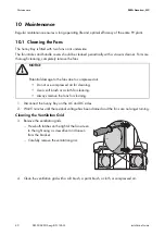
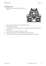
Страница 78: ...connect the Sunny Boy on the AC and DC sides 2 Wait 5 minutes until the residual voltage has been drained and the fans are no longer turning Cleaning the Ventilation Grid 3 Remove the ventilation grid...

Страница 79: ...owly and carefully downward 7 Unlock and remove the plug The cables of the fans are long enough to disconnect the plug in the inside of the Sunny Boy 8 Remove the fan 9 Clean the fans with a soft brus...

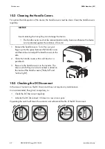
Страница 80: ...vers on the inverter The side on which they are to be mounted is stated on the inside of the handle covers links left and rechts right 10 3 Checking the DC Disconnect In the case of normal use the DC...

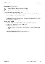
Страница 81: ...checking the fans is included in the scope of supply of the Sunny Boy Setting the Parameter 1 Ask for the installer password from SMA Serviceline See Contact on page 101 2 Set the Fan Test parameter...
Страница 82: ...rained 2 Open the Sunny Boy as described in section 6 2 Opening the Sunny Boy page 38 3 Insert the jumper supplied into the slot on the sequential control board shown below 4 Close the Sunny Boy as de...

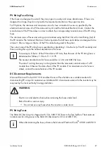
Страница 83: ...pen the Sunny Boy as described in section 6 2 Opening the Sunny Boy page 38 2 Replace the fuse A For the correct position of the fuse observe section DC Input Grounding on page 49 3 Completely insert...

Страница 84: ...Boy on the AC and DC sides 2 Wait 5 minutes until the residual voltage has been drained 3 Open the SMA DC Disconnect as described in section 6 3 Opening the SMA DC Disconnect page 39 4 Replace the fu...

Страница 85: ...ng this up to the nearest standard size for fuses DC Disconnect Requirements National Electrical Code 690 15 18 enables the use of fuse holders as a suitable medium for disconnecting PV arrays for mai...

Страница 86: ...in houses This device generates uses and can radiate radio frequency energy and if not installed and used in accordance with the instructions may cause harmful interference to radio communications Ho...

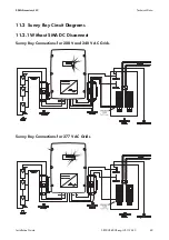
Страница 87: ...chnical Data Installation Guide SB50US 80US eng IUS112633 89 11 2 Sunny Boy Circuit Diagrams 11 2 1 Without SMA DC Disconnect Sunny Boy Connections for 208 V and 240 V AC Grids Sunny Boy Connections f...

Страница 88: ...Technical Data SMA America LLC 90 SB50US 80US eng IUS112633 Installation Guide 11 2 2 With SMA DC Disconnect Sunny Boy Connections for 208 V and 240 V AC Grids Sunny Boy Connections for 277 V AC Grids...

Страница 89: ...ing voltage range at 208 V nominal value 183 V 229 V AC operating voltage range at 240 V nominal value 211 V 264 V AC operating voltage range at 277 V nominal value 244 V 305 V AC operating frequency...

Страница 90: ...ominal value 0 99 Peak inverter efficiency 96 8 CEC weighted efficiency 95 5 Ambient temperature range SB 5000US 13 F 113 F 25 C 45 C Ambient temperature range SB 5000US 11 40 F 113 F 40 C 45 C Width...

Страница 91: ...e range at 208 V nominal value 183 V 229 V AC operating voltage range at 240 V nominal value 211 V 264 V AC operating voltage range at 277 V nominal value 244 V 305 V AC operating frequency range 59 3...

Страница 92: ...CEC weighted efficiency at 208 V AC 95 5 CEC weighted efficiency at 240 V AC 95 5 CEC weighted efficiency at 277 V AC 96 0 Ambient temperature range SB 6000US 13 F 113 F 25 C 45 C Ambient temperature...

Страница 93: ...age range at 208 V nominal value 183 V 229 V AC operating voltage range at 240 V nominal value 211 V 264 V AC operating voltage range at 277 V nominal value 244 V 305 V AC operating frequency range 59...

Страница 94: ...CEC weighted efficiency at 208 V AC 95 5 CEC weighted efficiency at 240 V AC 96 0 CEC weighted efficiency at 277 V AC 96 0 Ambient temperature range SB 7000US 13 F 113 F 25 C 45 C Ambient temperature...

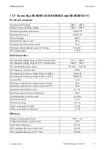
Страница 95: ...age range at 277 V nominal value 244 V 305 V AC operating frequency range 59 3 Hz 60 5 Hz AC frequency nominal value 60 Hz AC Maximum Continuous Output Power at 240 V 7 680 W AC Maximum Continuous Out...

Страница 96: ...Ambient temperature range SB 8000US 13 F 113 F 25 C 45 C Ambient temperature range SB 8000US 11 40 F 113 F 40 C 45 C Width x height x depth 183 8 in x 241 8 in x 91 16 in 468 mm x 613 mm x 242 mm Wei...

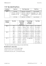
Страница 97: ...0 16 s 300 s standard max 0 1602 s 57 0 Hz 56 95 Hz 57 05 Hz max 0 1602 s Nominal Voltage Trip Limit Trip Voltages Conductor Neutral Conductor Trip Voltages Conductor Conductor Trip Times 208 V 50 88...

Страница 98: ...n terminal blocks for wires not used in the configuration of the AC voltage Phoenix 15 in lbs 1 7 Nm AC DC terminal blocks SMA DC Disconnect 15 in lbs 1 7 Nm 10 6 AWG Combined terminal block SMA DC Di...

Страница 99: ...of communication Sunny Boy disturbance or warning number Sunny Boy display message SMA Solar Technology America LLC 6020 West Oaks Blvd Ste 300 Rocklin CA 95765 Tel 1 916 625 0870 Tel 1 877 MY SMA TEC...

Отзывы: