SMA Solar Technology AG
3 Configuring Integrated Plant Control
Technical Information
IPC_STP-TI-en-14
9
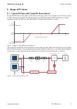
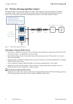
Parameter Description
3.3 Changing Inverter Operating Parameters
Always change operating parameters as described in this section. Some parameters that have sensitive functions can only
be viewed and changed by qualified persons (for further information on changing parameters, refer to the manual of the
communication product).
The operating parameters of the inverter are set to certain values by default. To optimize inverter operation, you can
change the operating parameters using a communication product.
Requirements:
☐ Depending on the type of communication, a computer with a BLUETOOTH or Ethernet interface must be available.
☐ A communication product corresponding to the type of communication used must be available.
☐ The inverter must be registered in the communication product.
☐ The changes to the grid-relevant parameters must be approved by the responsible grid operator.
☐ For changing the grid-relevant parameters, the SMA Grid Guard code must be available (see "Application for SMA
Grid Guard Code" at www.SMA-Solar.com).
Procedure:
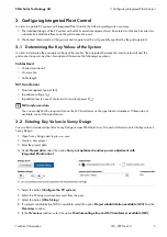
1. Call up the user interface of the communication product or software and log in as
Installer
or
User
.
2. If required, enter the SMA Grid Guard code.
3. Select and set the required parameter.
4. Save settings.
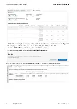
Parameter name for BLUETOOTH or
Speedwire/Webconnect
Parameter name
for RS485
Description
Rated apparent power of all inverters
Plnt.VARtg
Nominal apparent power of all inverters [kVA]
Ohmic resistance for impedance
compensation
ImpCpn.OhmRis
Ohmic resistance for impedance compensation
[ Ω ]
Inductive resistance for impedance
compensation
ImpCpn.IndRis
Lagging resistance for impedance compensation
[ Ω ]
Capacitive resistance for impedance
compensation
ImpCpn.CapacRis
Leading resistance for impedance compensation
[ Ω ]
Impedance compensation switched on
ImpCpn.IsOn
Impedance compensation switched on
/05*$&
Restricted function of Integrated Plant Control as a result of incorrect settings
If the required parameters for Integrated Plant Control are incorrectly calculated or if the parameters are entered
incorrectly in the inverter, the functioning of Integrated Plant Control is restricted. SMA Solar Technology AG does not
accept liability for incorrect entries made by customers.
• For error-free functioning of Integrated Plant Control, the system must be modeled correctly using Sunny Design.
• If required, and subject to a fee, SMA Solar Technology AG can provide assistance with the correct calculation
of the system parameters and with system parameterization.

