background image

1  Information on this Document

SMA Solar Technology AG

Replacement Manual

STP50-40-COM-RM-xx-11

6

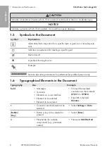
CAUTION

Indicates a hazardous situation which, if not avoided, could result in minor or moderate injury.

NOTICE

Indicates a situation which, if not avoided, can result in property damage.

1.5

Symbols in the Document

Symbol

Explanation

Information that is important for a specific topic or goal, but is not safety-rele-
vant

Indicates a requirement for meeting a specific goal

Desired result

A problem that might occur

Example

Sections describing activities to be performed by qualified persons only

1.6

Typographical Elements in the Document

Typography

Use

Example

bold

• Messages
• Terminals
• Elements on a user interface
• Elements to be selected
• Elements to be entered

• Connect the insulated

conductors to the terminals

X703:1

 to 

X703:6

.

• Enter 

10

 in the field

Minutes

.

>

• Connects several elements to be

selected

• Select 

Settings > Date

.

[

Button

]

[

Key

]

• Button or key to be selected or

pressed

• Select [

Enter

].

#

• Placeholder for variable

components (e.g., parameter
names)

• Parameter 

WCtlHz.Hz#

ENGLISH

Содержание NR-PC-KP20L.BG1

Страница 1: ...OM RM xx 11 105524 00 03 Version 1 1 Spare part set Communication Assembly for SUNNY TRIPOWER CORE1 STP 50 40 CORE1 US STP 50 US 40 STP 33 US 41 STP 50 US 41 STP 62 US 41 CORE1 JP STP 50 JP 40 NR PC K...

Страница 2: ...v m n 43 63 ESPA OL Instrucciones para la sustituci n 84 FRAN AIS Instructions de remplacement 105 ITALIANO Istruzioni per la sostituzione 126 NEDERLANDS Vervangingshandleiding 147 PORTUGU S Manual d...

Страница 3: ...ny indirect incidental or consequential damages under any circumstances The exclusion of implied warranties may not apply in all cases under some statutes and thus the above exclusion may not apply Sp...

Страница 4: ...ssages 5 1 5 Symbols in the Document 6 1 6 Typographical Elements in the Document 6 1 7 Designations in the Document 7 2 Safety 8 2 1 Intended Use 8 2 2 IMPORTANT SAFETY INSTRUCTIONS 8 3 Scope of Deli...

Страница 5: ...scribed in this document This ensures the quality requirements for proper replacement of assemblies The type of training and the media used may vary from country to country Knowledge of how to safely...

Страница 6: ...rement for meeting a specific goal Desired result A problem that might occur Example Sections describing activities to be performed by qualified persons only 1 6 Typographical Elements in the Document...

Страница 7: ...Technology AG Replacement Manual STP50 40 COM RM xx 11 7 1 7 Designations in the Document Complete designation Designation in this document Sunny Tripower CORE1 Inverter product Communication assembl...

Страница 8: ...convenient dry place for future reference and observe all instructions contained therein This document does not replace and is not intended to replace any local state provincial federal or national la...

Страница 9: ...cables Touching live DC cables results in death or lethal injuries due to electric shock Do not touch non insulated parts or cables Disconnect the inverter from voltage sources and make sure it canno...

Страница 10: ...tection WARNING Risk of injury due to toxic substances gases and dusts In rare cases damages to electronic components can result in the formation of toxic substances gases or dusts inside the inverter...

Страница 11: ...nclosure openings NOTICE Damage to the inverter due to electrostatic discharge Touching electronic components can cause damage to or destroy the inverter through electrostatic discharge Ground yoursel...

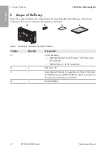
Страница 12: ...DISPLAY BAT Max 30V DC USB FCC ID SVF KP IC 9440A KP20 MFR A B X1 X2 D C B Figure 1 Components included in the scope of delivery Position Quantity Designation A 1 COM assembly NR PC KP20L BG1 f r STP...

Страница 13: ...e inverter to position O 3 Set the DC load break switch of the inverter to position O 4 If the multifunction relay is used switch off any supply voltage to the load 5 Wait until the LEDs have gone out...

Страница 14: ...are equipped with DC conductors are in perfect condition and that none of the DC conductors or DC plug contacts are exposed 12 Ensure that no voltage is present at the DC inputs on the inverter using...

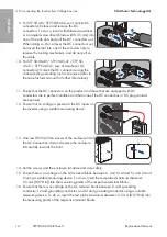
Страница 15: ...included in STP50 US 40 STP 33 US 41 STP 50 US 41 and STP 62 US 41 Procedure 1 Disconnect the inverter from all voltage sources see Section 4 page 13 2 Release TX25 all 10 screws of the enclosure lid...

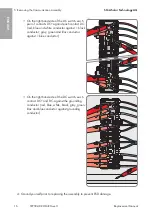
Страница 16: ...contact DC red blue and white conductor against 1 black conductor gray green and lilac conductor against 1 blue conductor On the right hand side of the DC switch each contact DC and DC against the gr...

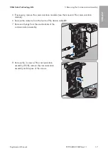
Страница 17: ...cable tie from the ferrite of the ribbon cable X1 7 Remove all plugs from the used sockets of the communication assembly X2 Max 30V DC USB M2 FCC ID SVF KP20 IC 9440A KP20 ANT SPS B A X1 M1 MFR BAT 8...

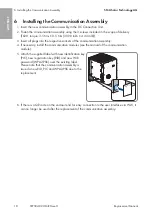
Страница 18: ...spective sockets of the communication assembly 4 If necessary install the communication modules see the manual of the communication module 5 Attach the supplied label with new identification key PIC n...

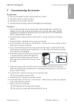
Страница 19: ...ch is turned to position 0 5 To avoid invalid serial numbers from being sent to the data logger commission the inverter without being connected to the local network first To do this ensure that the RJ...

Страница 20: ...ed out 15 If the red LED lights up an event has occurred Find out which event has occurred and if necessary initiate countermeasures 16 Update the inverter network settings and integrate the inverter...

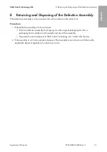
Страница 21: ...rder form Procedure 1 If the defective assembly is to be returned Pack the defective assembly for shipping Use the original packaging for this or packaging that is suitable for the weight and size of...

Страница 22: ...zuf llige Folgeverluste oder Sch den Der oben genannte Ausschluss von impliziten Gew hrleistungen kann nicht in allen F llen angewendet werden nderungen an Spezifikationen bleiben vorbehalten Es wurde...

Страница 23: ...nhinweisstufen 24 1 5 Symbole im Dokument 25 1 6 Auszeichnungen im Dokument 25 1 7 Benennungen im Dokument 26 2 Sicherheit 27 2 1 Bestimmungsgem e Verwendung 27 2 2 Wichtige Sicherheitshinweise 27 3 L...

Страница 24: ...m SMA Schulungsangebot zur Durchf hrung der in diesem Dokument beschriebenen T tigkeiten Dadurch werden die Qualit tsanforderungen f r einen ordnungsgem en Austausch von Baugruppen sichergestellt Die...

Страница 25: ...n bestimmtes Thema oder Ziel wichtig aber nicht sicher heitsrelevant ist Voraussetzung die f r ein bestimmtes Ziel gegeben sein muss Erw nschtes Ergebnis M glicherweise auftretendes Problem Beispiel K...

Страница 26: ...aste Schaltfl che oder Taste die Sie w hlen oder dr cken sollen Enter w hlen Platzhalter f r variable Bestandteile z B in Parameternamen Parameter WCtlHz Hz 1 7 Benennungen im Dokument Vollst ndige Be...

Страница 27: ...er Eingriffe ist ausgeschlossen Jede andere Verwendung des Produkts als in der bestimmungsgem en Verwendung beschrieben gilt als nicht bestimmungsgem Die beigef gten Dokumentationen sind Bestandteil d...

Страница 28: ...spannungsf hrender Teile oder Kabel des Wechselrichters f hrt zum Tod oder zu lebensgef hrlichen Verletzungen durch Stromschlag Vor Arbeiten den Wechselrichter spannungsfrei schalten und gegen Wieder...

Страница 29: ...Fehlerfall im Inneren des Wechselrichters ein z ndf higes Gasgemisch entstehen Durch Schalthandlungen kann in diesem Zustand im Inneren des Wechselrichters ein Brand entstehen oder eine Explosion aus...

Страница 30: ...Spannung am Geh use des Messger ts f hren Das Ber hren des unter Spannung stehenden Geh uses des Messger tes f hrt zum Tod oder zu lebensgef hrlichen Verletzungen durch Stromschlag Nur Messger te mit...

Страница 31: ...en Erden Sie sich bevor Sie ein Bauteil ber hren Schutzleiterpr fung vor Wiederinbetriebnahme Vor der Wiederinbetriebnahme von SMA Wechselrichtern nach Einbau von nicht intuitiv zu tauschenden SMA Kom...

Страница 32: ...ung A DISPLAY BAT Max 30V DC USB FCC ID SVF KP IC 9440A KP20 MFR A B X1 X2 D C B Abbildung 1 Bestandteile des Lieferumfangs Position Anzahl Bezeichnung A 1 COM Baugruppe NR PC KP20L BG1 f r STP 50 40...

Страница 33: ...den Geh uses des Messger tes f hrt zum Tod oder zu lebensgef hrlichen Verletzungen durch Stromschlag Nur Messger te mit einem DC Eingangsspannungsbereich bis mindestens 1000 V oder h her einsetzen Vor...

Страница 34: ...C Steckerkontakte freigelegt sind Die DC Steckverbinder vorsichtig entriegeln und abziehen wie im Folgenden beschrieben 9 Bei STP 50 40 STP 50 JP 40 Verwendung von Sunclix DC Steckverbindern Die DC St...

Страница 35: ...ie Schrauben und den Geh usedeckel zu Seite legen und sicher aufbewahren 15 Spannungsfreiheit an der AC Klemmleiste zwischen L1 und N L2 und N und L3 und N mit geeignetem Messger t feststellen Dazu di...

Страница 36: ...lie lich in STP50 US 40 STP 33 US 41 STP 50 US 41 und STP 62 US 41 vorhanden Vorgehen 1 Den Wechselrichter spannungsfrei schalten siehe Kapitel 4 Seite 33 2 Alle 10 Schrauben des Geh usedeckels der DC...

Страница 37: ...jeden Kontakt DC den roten blauen und wei en Leiter gegen 1 schwarzen Leiter sowie den grauen gr nen und lila Leiter gegen 1 blauen Leiter Auf der rechten Seite des DC Schalters jeden Kontakt DC und...

Страница 38: ...des Flachbandkabels X1 entfernen 7 Alle Stecker aus den verwendeten Buchsen der Kommunikationsbaugruppe abziehen X2 Max 30V DC USB M2 FCC ID SVF KP20 IC 9440A KP20 ANT SPS B A X1 M1 MFR BAT 8 Die 3 S...

Страница 39: ...ruppe stecken 4 Gegebenenfalls Kommunikationsmodule einbauen siehe Anleitung des Kommunikationsmoduls 5 Mitgelieferten Aufkleber mit neuem Identifizierungsschl ssel PIC neuem Registrierungsschl ssel R...

Страница 40: ...osition 0 steht 5 Um zu vermeiden dass ung ltige Seriennummern an den Datenlogger bertragen werden den Wechselrichter zun chst ohne Einbindung in das lokale Netzwerk in Betrieb nehmen Dazu sicherstell...

Страница 41: ...eignis an Finden Sie heraus welches Ereignis anliegt und leiten Sie gegebenenfalls Ma nahmen ein 16 Die Netzwerkeinstellungen des Wechselrichters aktualisieren und den Wechselrichter in das lokale Net...

Страница 42: ...hen 1 Wenn die defekte Baugruppe zur ckgesendet werden soll Die defekte Baugruppe f r den Versand verpacken Dabei die Originalverpackung oder eine Verpackung verwenden die sich f r Gewicht und Gr e de...

Страница 43: ...p m i n hodn n sledn ztr ty nebo kody V e uvedenou v luku implicitn ch z ruk nelze aplikovat ve v ech p padech Vyhrazujeme si pr vo na zm ny specifikac Maxim ln usilujeme o to abychom tento dokument v...

Страница 44: ...upozorn n 45 1 5 Symboly v dokumentu 46 1 6 Typografick konvence v dokumentu 46 1 7 Ozna en v tomto dokumentu 47 2 Bezpe nost 48 2 1 Pou it v souladu s ur en m 48 2 2 D le it bezpe nostn upozorn n 48...

Страница 45: ...echnology AG k prov d n innost popsan ch v tomto dokumentu ast na kolen spole nosti SMA T m zajist te spln n kvalitativn ch po adavk pro dnou v m nu konstruk n ch skupin Druh kolen a pou it m dia se m...

Страница 46: ...Informace kter je pro ur it t ma nebo ur it c l d le it ale net k se bez pe nosti Podm nka kter mus b t pro dosa en ur it ho c le spln na douc v sledek Probl m kter se m e vyskytnout P klad Kapitola...

Страница 47: ...tko na kter je t eba kliknout nebo kl vesa kterou je t eba stisknout Stiskn te kl vesu Enter Z stupce variabiln ch sou st nap v n zvech parametr Parametr WCtlHz Hz 1 7 Ozna en v tomto dokumentu Pln o...

Страница 48: ...ology AG za kody zp soben v d sledku takov ch z sah je vylou ena Jak koliv jin pou it produktu ne je pops no v pou it v souladu s ur en m se pova uje za pou it v rozporu s ur en m P ilo en dokumentace...

Страница 49: ...tomn vysok nap t Kontakt s d ly nebo kabely st da e pod nap t m zap in smrteln raz nebo t k poran n v d sledku z sahu elektrick m proudem P ed prov d n m prac st da odpojte od nap t a zajist te ho pr...

Страница 50: ...mi d ly V p pad poruchy neprov d jte na st da i dn p m kony Zajist te aby ke st da i nem ly p stup nepovolan osoby Na st da i nepou vejte DC odp na z t e FV gener tor odpojte od st da e extern m odpo...

Страница 51: ...t sn n krytu p i mrazu Pokud st da otev ete p i mrazu m e se po kodit t sn n krytu Do st da e tak m e vnikat vlhkost kter ho po kod St da otv rejte jen tehdy pokud teplota okol neklesne pod 5 C Je li...

Страница 52: ...vodi Mus b t zaji t na funkce ochrann ho vodi e a dodr eny v echny z kony normy a sm rnice platn v m st pou it Dodr ujte nad azen standardy Za opravu p stroje a zohledn n a aplikaci dal ch norem kter...

Страница 53: ...jce A DISPLAY BAT Max 30V DC USB FCC ID SVF KP IC 9440A KP20 MFR A B X1 X2 D C B Obr zek 1 sou sti dod vky Polo ka Po et Ozna en A 1 Konstruk n skupina COM NR PC KP20L BG1 pro STP 50 40 STP 50 US 40 S...

Страница 54: ...na z t e st da e nastavte do polohy O 4 Pokud se pou v multifunk n rel p padn vypn te nap jec nap t spot ebi e 5 Po kejte ne LED diody zhasnou 6 Amp rmetrov mi kle t mi ov te zda jednotliv mi DC kabe...

Страница 55: ...11 Zajist te aby DC konektory na produktu a DC konektory opat en DC vodi i byly v bezvadn m stavu a DC vodi e nebo kontakty konektor nebyly obna en 12 Pomoc vhodn ho m ic ho p stroje ov te zda na DC v...

Страница 56: ...na instalov n v hradn v STP50 US 40 STP 33 US 41 STP 50 US 41 a STP 62 US 41 Postup 1 Odpojte st da od nap t viz kapitola 4 strana 54 2 Vy roubujte v ech 10 roub v ka krytu jednotky DC Connection Unit...

Страница 57: ...akt DC proti ka d mu kontaktu DC erven modr a b l vodi proti 1 ern mu vodi i a ed zelen a fialov vodi proti 1 modr mu vodi i Na prav stran DC vyp na e ka d kontakt DC a DC proti PE erven modr b l ern...

Страница 58: ...ploch ho kabelu X1 odstra te v zac p sek 7 Z pou van ch z suvek komunika n ho modulu vypojte v echny konektory X2 Max 30V DC USB M2 FCC ID SVF KP20 IC 9440A KP20 ANT SPS B A X1 M1 MFR BAT 8 Vy roubujt...

Страница 59: ...ho modulu zapojte v echny konektory 4 P padn namontujte komunika n moduly viz n vod komunika n ho modulu 5 St vaj c n lepku p elepte dodanou n lepkou s nov m k dem PIC nov m registra n m k dem RID a n...

Страница 60: ...t e nach zel v poloze 0 5 Chcete li zamezit tomu aby se do dataloggeru p en ela neplatn s riov sla st da nejprve uve te do provozu bez p ipojen k m stn s ti Za t mto elem zajist te aby nebylo nav z no...

Страница 61: ...tak prob hnout aktualizace st da e 15 Pokud sv t erven LED dioda do lo k ud losti Zjist te o jakou ud lost se jedn a p padn prove te pot ebn opat en 16 Aktualizujte s ov nastaven st da e a st da p ip...

Страница 62: ...i objedn vky Postup 1 Pokud je t eba vadnou konstruk n skupinu zaslat zp t Zabalte vadnou konstruk n skupinu pro odesl n Pou ijte k tomu p vodn obal nebo jin obal kter vyhovuje hmotnosti a velikosti...

Страница 63: ...Solar Technology AG SMA Solar Technology AG SMA Solar Technology AG SMA Solar Technology AG SMA Solar Technology AG SMA Solar Technology AG Sonnenallee 1 34266 Niestetal 49 561 9522 0 49 561 9522 100...

Страница 64: ...SMA Solar Technology AG STP50 40 COM RM xx 11 64 1 65 1 1 65 1 2 65 1 3 65 1 4 65 1 5 66 1 6 67 1 7 67 2 68 2 1 68 2 2 68 3 73 4 74 5 77 6 80 7 81 8 83...

Страница 65: ...gy AG STP50 40 COM RM xx 11 65 1 1 1 NR PC KP20L BG1 STP 50 40 STP 50 US 40 STP 50 JP 40 NR PL KP20 41 1 STP33 US 41 STP50 US 41 STP62 US 41 1 2 SMA SMA Solar Technology AG SMA SMA SMA Solar Technolog...

Страница 66: ...1 SMA Solar Technology AG STP50 40 COM RM xx 11 66 1 5...

Страница 67: ...1 SMA Solar Technology AG STP50 40 COM RM xx 11 67 1 6 X703 1 X703 6 10 Enter WCtlHz Hz 1 7 Sunny Tripower CORE1 COM COM COM...

Страница 68: ...RM xx 11 68 2 2 1 COM SMA SMA NR PC KP20L BG1 STP 50 40 STP 50 JP 40 STP 50 US 40 NR PL KP20 41 1 STP33 US 41 STP50 US 41 STP62 US 41 SMA SMA Solar Technology AG SMA Solar Technology AG SMA Solar Tec...

Страница 69: ...2 SMA Solar Technology AG STP50 40 COM RM xx 11 69 5 DC DC DC DC...

Страница 70: ...2 SMA Solar Technology AG STP50 40 COM RM xx 11 70 5 DC DC AC...

Страница 71: ...2 SMA Solar Technology AG STP50 40 COM RM xx 11 71 DC 1000 V DC 5 C...

Страница 72: ...2 SMA Solar Technology AG STP50 40 COM RM xx 11 72 v v SMA SMA SMA Solar Technology AG...

Страница 73: ...OM RM xx 11 73 3 A DISPLAY BAT Max 30V DC USB FCC ID SVF KP IC 9440A KP20 MFR A B X1 X2 D C B 1 A 1 COM NR PC KP20L BG1 STP 50 40 STP 50 US 40 STP 50 JP 40 NR PL KP20 41 1 STP xxx US 41 B 3 M4x15 C 1...

Страница 74: ...4 SMA Solar Technology AG STP50 40 COM RM xx 11 74 4 DC 1000 V 1 AC 2 STP 50 US 40 STP 33 U S 41 STP 50 US 41 STP 62 US 41 AC O 3 DC O 4 5 LED 6 DC 0 5A 0 5A 7 DC...

Страница 75: ...AG STP50 40 COM RM xx 11 75 8 DC DC DC DC DC DC DC DC DC DC DC DC DC DC DC 9 STP 50 40 STP 50 JP 40 DC Sunclix DC 3 5 mm DC DC 1 2 10 STP 50 US 40 STP 33 US 41 STP 50 US 41 STP 62 US 41 DC Amphenol DC...

Страница 76: ...4 SMA Solar Technology AG STP50 40 COM RM xx 11 76 12 DC A B C 30V 13 10 AC Connection Unit 25 10x 14 15 AC L1 N L2 N L3 N 2 5 mm 0 078 in 16 AC L1 PE L2 PE L3 PE 2 5 mm 0 078 in...

Страница 77: ...SMA Solar Technology AG STP50 40 COM RM xx 11 77 5 DC Connection Unit COM LED A 2 A AC STP50 US 40 STP 33 US 41 STP 50 US 41 STP 62 US 41 1 4 74 2 10 DC Connection Unit 25 10x 3 DC Connection Unit 5...

Страница 78: ...5 SMA Solar Technology AG STP50 40 COM RM xx 11 78 DC DC DC 1 1 DC DC DC PE PE 4...

Страница 79: ...nology AG STP50 40 COM RM xx 11 79 5 6 X1 7 X2 Max 30V DC USB M2 FCC ID SVF KP20 IC 9440A KP20 ANT SPS B A X1 M1 MFR BAT 8 3 TX20 X2 Max 30V DC USB M2 FCC ID SVF KP20 IC 9440A KP20 ANT SPS B A X1 M1 M...

Страница 80: ...6 SMA Solar Technology AG STP50 40 COM RM xx 11 80 6 1 DC Connection Unit 2 3 TX20 3 5 Nm 0 5 Nm 30 98 in lb 4 43 in lb 3 4 5 PIC RID WLAN WPA2 PSK RID PIC WPA2 PSK _ _ PIC RID PSK 6 QR WLAN...

Страница 81: ...50 US 40 STP 33 US 41 STP 50 US 41 STP 62 US 41 C 0 5 RJ45 6 C Connection Unit C Connection Unit TX25 6 Nm 53 in lb 2 1 10x 10x 7 DC Connection Unit DC Connection Unit TX25 6 Nm 53 in lb 8 DC DC 9 DC...

Страница 82: ...7 SMA Solar Technology AG STP50 40 COM RM xx 11 82 12 DC I 13 LED LED 14 15 15 LED 16 17 QR WLAN 18 Sunny Portal Sunny Portal SMA www SMA Solar com 19...

Страница 83: ...8 SMA Solar Technology AG STP50 40 COM RM xx 11 83 8 1 SMA Solar Technology AG 2...

Страница 84: ...ltante bajo ninguna circunstancia La exclusi n de garant as impl citas puede no ser aplicable en todos los casos seg n algunos estatutos y por tanto la exclusi n mencionada anteriormente puede no ser...

Страница 85: ...ia 86 1 5 S mbolos del documento 87 1 6 Marcas de texto en el documento 87 1 7 Denominaci n en el documento 88 2 Seguridad 89 2 1 Uso previsto 89 2 2 Indicaciones importantes para la seguridad 89 3 Co...

Страница 86: ...la participaci n en una formaci n de SMA para llevar a cabo las tareas descritas en el presente documento As se garantizan los requisitos de calidad necesarios para sustituir correctamente los subgrup...

Страница 87: ...o Explicaci n Informaci n importante para un tema u objetivo concretos aunque no rele vante para la seguridad Requisito necesario para alcanzar un objetivo determinado Resultado deseado Posible proble...

Страница 88: ...otones o teclas que deben seleccionarse o pulsarse Seleccione Enter Car cter comod n para componentes variables p ej en nombres de par metros Par metro WCtlHz Hz 1 7 Denominaci n en el documento Denom...

Страница 89: ...chnology AG por los da os derivados de dichos cambios Cualquier uso del producto distinto al descrito en el uso previsto se considerar inadecuado La documentaci n adjunta es parte integrante del produ...

Страница 90: ...s del inversor puede causar la muerte o lesiones mortales por descarga el ctrica Antes de cualquier trabajo desconecte el inversor y asegure el producto contra cualquier reconexi n accidental Despu s...

Страница 91: ...puede producirse en caso de error una mezcla de gas inflamable en el interior del inversor En este estado puede producirse un incendio en el interior del inversor o una explosi n durante las activida...

Страница 92: ...e da ar un equipo de medici n y provocar que exista tensi n en la carcasa del equipo de medici n Tocar la carcasa del equipo de medici n bajo tensi n puede causar la muerte o lesiones mortales por des...

Страница 93: ...r cualquier componente Comprobaci n del cable a tierra antes de la nueva puesta en marcha Antes de la nueva puesta en marcha de los inversores de SMA despu s de instalar componentes de SMA o subgrupos...

Страница 94: ...n su distribuidor A DISPLAY BAT Max 30V DC USB FCC ID SVF KP IC 9440A KP20 MFR A B X1 X2 D C B Imagen 1 Componentes del contenido de la entrega Posici n Cantidad Denominaci n A 1 Subgrupo COM NR PC KP...

Страница 95: ...n bajo tensi n puede causar la muerte o lesiones mortales por descarga el ctrica Use solo equipos de medici n con un rango de tensi n de entrada de CC de hasta 1000 V como m nimo Procedimiento 1 Desc...

Страница 96: ...no haya cables de CC o contactos de conexi n CC al descubierto Desbloquear y extraer los conectadores de enchufe con cuidado tal y como se describe a continuaci n 9 En STP 50 40 STP 50 JP 40 utilizaci...

Страница 97: ...10x 14 Aparte y guarde en un lugar seguro la tapa de la carcasa y los tornillos 15 Compruebe con un de medici n adecuado que no haya tensi n en la caja de bornes de AC entre L1 y N L2 y N y L3 y N Pa...

Страница 98: ...lusivamente en STP50 US 40 STP 33 US 41 STP 50 US 41 y STP 62 US 41 Procedimiento 1 Desconecte el inversor de la tensi n consulte el cap tulo 4 p gina 95 2 Suelte los diez tornillos de la tapa de la c...

Страница 99: ...s conductores rojo azul y blanco contra un cable negro y los cables gris verde y morado contra un cable azul Descargue en el lado derecho del interruptor de CC cada contacto de CC y CC contra el condu...

Страница 100: ...abrazadera para cables de la ferrita del cable plano X1 7 Retire todos los conectores de los conectores hembra utilizados del subgrupo de comunicaci n X2 Max 30V DC USB M2 FCC ID SVF KP20 IC 9440A KP...

Страница 101: ...grupo de comunicaci n 4 En caso necesario monte los m dulos de comunicaci n consulte las instrucciones del m dulo de comunicaci n 5 Pegue el adhesivo suministrado sobre el existente adhesivo con un nu...

Страница 102: ...eccionador de potencia de CA se encuentre en la posici n 0 5 Para evitar que se transfieran n meros de serie no v lidos al registrador de datos ponga inicialmente el inversor en funcionamiento sin int...

Страница 103: ...y un evento Averig e de qu evento se trata y en caso necesario emprenda las medidas necesarias 16 Actualice los ajustes de red del inversor y conecte el inversor a la red local consulte las instruccio...

Страница 104: ...subgrupo averiado Procedimiento 1 Si debe devolverse el subgrupo averiado Embale el subgrupo averiado para su env o Utilice para ello el embalaje original o bien otro que sea adecuado para el peso y...

Страница 105: ...ectifs ne sauraient et ce sous aucune circonstance tre tenus responsables en cas de pertes ou de dommages directs indirects ou accidentels L exclusion susmentionn e des garanties implicites peut ne pa...

Страница 106: ...5 Symboles utilis s dans le document 108 1 6 Formats utilis s dans le document 108 1 7 D signations utilis es dans le document 109 2 S curit 110 2 1 Utilisation conforme 110 2 2 Consignes de s curit i...

Страница 107: ...ticiper une formation SMA pour ex cuter les op rations d crites dans ce document Cela permet de garantir que les exigences de qualit pour un remplacement en bonne et due forme des ensembles sont satis...

Страница 108: ...mbole Explication Information importante sur un th me ou un objectif pr cis mais ne relevant pas de la s curit Condition qui doit tre remplie pour atteindre un objectif pr cis R sultat souhait Probl m...

Страница 109: ...e que vous devez s lectionner ou actionner S lectionnez Enter Caract res de remplacement pour les composants variables par exemple dans les noms de param tres Param tre WCtlHz Hz 1 7 D signations util...

Страница 110: ...cas de dommages r sultant d une telle intervention Toute utilisation du produit diff rente de celle d crite dans l utilisation conforme est consid r e comme non conforme Les documents joints font par...

Страница 111: ...nts conducteurs ou des c bles de l onduleur peut entra ner la mort ou des blessures mortelles due un choc lectrique Mettez hors tension l onduleur et s curisez le avant toute intervention Apr s la mis...

Страница 112: ...gazeux inflammables peuvent tre g n r s dans l onduleur en cas de dysfonctionnement Les op rations de commutation risquent dans ce cas de provoquer un incendie ou une explosion dans l onduleur Il peut...

Страница 113: ...ension peut endommager un appareil de mesure et cr er une tension au niveau du bo tier de l appareil de mesure Le contact avec le bo tier sous tension de l appareil de mesure entra ne des blessures gr...

Страница 114: ...terre avant de toucher un composant Contr le du conducteur de protection avant la remise en service Avant la remise en service d onduleurs SMA survenant apr s l installation de composants ou de module...

Страница 115: ...USB FCC ID SVF KP IC 9440A KP20 MFR A B X1 X2 D C B Figure 1 l ments du contenu de livraison Position Quantit D signation A 1 Ensemble COM NR PC KP20L BG1 f r STP 50 40 STP 50 US 40 STP 50 JP 40 NR PL...

Страница 116: ...de mesure entra ne des blessures graves voire la mort par choc lectrique Utilisez exclusivement des appareils de mesure avec une plage de tension d entr e DC d au moins 1000 V ou sup rieure Proc dure...

Страница 117: ...lez et retirez les connecteurs DC avec pr caution comme d crit ci apr s 9 Pour les STP 50 40 STP 50 JP 40 utilisation de connecteurs DC SUNCLIX d verrouillez et retirez les connecteurs DC Ins rez un t...

Страница 118: ...adapt v rifiez que les plaques bornes AC entre L1 et N L2 et N et L3 et N sont bien hors tension Pour ce faire ins rez la pointe de contr le diam tre maximal 2 5 mm 0 078 in dans l ouverture de mesure...

Страница 119: ...ment dans les onduleurs STP50 US 40 STP 33 US 41 STP 50 US 41 et STP 62 US 41 Proc dure 1 Mettez l onduleur hors tension voir chapitre 4 page 116 2 D vissez les 10 vis du couvercle du bo tier de la Co...

Страница 120: ...eu et blanc contre un conducteur noir et le conducteur gris vert et violet contre un conducteur bleu Sur le c t droit de l interrupteur chaque contact DC et DC contre le conducteur de protection le co...

Страница 121: ...Retirez l attache c bles plac sur la ferrite du c ble plat X1 7 tez toutes les fiches des embases utilis es du groupe de communication X2 Max 30V DC USB M2 FCC ID SVF KP20 IC 9440A KP20 ANT SPS B A X1...

Страница 122: ...cas ch ant montez les modules de communication voir les instructions du module de communication 5 Collez l autocollant fourni sur lequel figurent le nouveau code d identification PIC le nouveau code...

Страница 123: ...surez vous que l interrupteur sectionneur AC est sur la position 0 5 Pour viter que des num ros de s rie non valides soient transmis l enregistreur de donn es d marrez l onduleur sans tre connect au r...

Страница 124: ...signifie qu un v nement est survenu Recherchez la nature de l v nement et prenez les mesures n cessaires 16 Actualisez les r glages r seau de l onduleur et int grez l onduleur dans le r seau local vo...

Страница 125: ...e Proc dure 1 Si le module de construction doit tre renvoy Emballez le module de construction d fectueux pour l exp dier Utilisez pour ce faire l emballage d origine ou un emballage appropri au poids...

Страница 126: ...eguenti o danni diretti o indiretti La suddetta esclusione di garanzie di legge implicite non si applica in altri casi Con riserva di modifiche delle specifiche stato fatto il possibile per redigere q...

Страница 127: ...urezza 128 1 5 Simboli nel documento 129 1 6 Convenzioni tipografiche nel documento 129 1 7 Denominazioni nel documento 130 2 Sicurezza 131 2 1 Utilizzo conforme 131 2 2 Avvertenze di sicurezza import...

Страница 128: ...di partecipare all offerta formativa di SMA per svolgere le attivit descritte nel presente documento In questo modo vengono garantiti i requisiti di qualit per la corretta sostituzione dei gruppi cos...

Страница 129: ...ia dal punto di vista della sicurezza Condizioni preliminari necessarie per un determinato obiettivo Risultato desiderato Possibile problema Esempio Capitolo in cui sono descritte operazioni che posso...

Страница 130: ...logy AG Istruzioni per la sostituzione STP50 40 COM RM xx 11 130 1 7 Denominazioni nel documento Denominazione completa Denominazione nel presente documento Sunny Tripower CORE1 Inverter prodotto Grup...

Страница 131: ...onsabilit di SMA Solar Technology AG per danni derivanti da tali interventi Non consentito alcun utilizzo del prodotto diverso da quanto specificato nel capitolo Utilizzo conforme La documentazione in...

Страница 132: ...con componenti sotto tensione o cavi dell inverter pu determinare la morte o lesioni mortali per folgorazione Prima di qualsiasi intervento togliere tensione all inverter e assicurarlo contro la riat...

Страница 133: ...ione In rari casi in presenza di un guasto pu crearsi una miscela di gas infiammabile all interno dell inverter In caso di attivazione tale situazione all interno dell inverter pu provocare un incendi...

Страница 134: ...causare la presenza di tensione sull involucro dell apparecchio di misurazione Il contatto con l involucro sotto tensione dell apparecchio di misurazione causa la morte o lesioni mortali per folgoraz...

Страница 135: ...e i componenti Verifica del conduttore di protezione prima della rimessa in funzione Prima di rimettere in funzione gli inverter SMA dopo il montaggio di componenti o gruppi di potenza SMA la cui sost...

Страница 136: ...ivolgersi al proprio rivenditore A DISPLAY BAT Max 30V DC USB FCC ID SVF KP IC 9440A KP20 MFR A B X1 X2 D C B Figura 1 Contenuto della fornitura Posizione Numero Denominazione A 1 Gruppo COM NR PC KP2...

Страница 137: ...involucro sotto tensione dell apparecchio di misurazione causa la morte o lesioni mortali per folgorazione Impiegare soltanto apparecchi di misurazione con un range di tensione d ingresso CC fino ad a...

Страница 138: ...C scoperti Sbloccare ed estrarre con attenzione tutti i terminali CC come descritto di seguito 9 Per STP 50 40 STP 50 JP 40 utilizzo di terminali CC Sunclix sbloccare ed estrarre i terminali CC A tal...

Страница 139: ...luogo sicuro le viti e il coperchio 15 Verificare l assenza di tensione sulla morsettiera CA fra L1 ed N L2 ed N ed L3 ed N con un apposito apparecchio di misurazione A tal fine inserire il puntale d...

Страница 140: ...nterruttore CA presente tranne in STP50 US 40 STP 33 US 41 STP 50 US 41 e STP 62 US 41 Procedura 1 Disinserire l inverter v cap 4 pag 137 2 Svitare tutte e 10 le viti del coperchio dell involucro dell...

Страница 141: ...ciascun contatto il conduttori rosso blu e bianco verso 1 conduttore nero nonch il conduttore grigio verde e lilla verso 1 conduttore blu Sulla destra dell interruttore CC scaricare ogni contatto CC e...

Страница 142: ...overe la fascetta serracavo sulla ferrite del cavo piatto X1 7 Estrarre tutti i connettori delle prese del gruppo di comunicazione utilizzate X2 Max 30V DC USB M2 FCC ID SVF KP20 IC 9440A KP20 ANT SPS...

Страница 143: ...i comunicazione 4 Eventualmente montare il gruppo di comunicazione v le istruzioni del modulo di comunicazione 5 Attaccare l adesivo in dotazione con la nuova chiave di identificazione PIC la nuova ch...

Страница 144: ...tore CC sia in posizione 0 5 Per evitare che i numeri di serie non validi vengano trasmessi al datalogger avviare inizialmente l inverter senza collegarlo alla rete locale A tal fine accertarsi che il...

Страница 145: ...15 Se il LED rosso acceso si verificato un evento Verificare l evento che si verificato ed eventualmente adottare dei provvedimenti 16 Aggiornare le impostazioni di rete dell inverter e collegare l in...

Страница 146: ...ocedura 1 Se un gruppo difettoso deve essere rispedito Imballare il gruppo difettoso per la spedizione Utilizzare l imballaggio originale o una confezione adatta al peso e alle dimensioni del gruppo O...

Страница 147: ...bovengenoemde uitsluiting van impliciete garanties kan niet in alle gevallen worden toegepast Wijzigingen van specificaties blijven voorbehouden Dit document is met veel inspanning en uiterst zorgvul...

Страница 148: ...heidswaarschuwing 149 1 5 Symbolen in het document 150 1 6 Markeringen in document 150 1 7 Benamingen in het document 151 2 Veiligheid 152 2 1 Reglementair gebruik 152 2 2 Belangrijke veiligheidsaanwi...

Страница 149: ...ren van de in dit document beschreven werkzaamheden Daardoor worden de kwaliteitseisen voor een correcte vervanging van modules gewaarborgd De inhoud van de scholing en de gebruikte media kunnen per l...

Страница 150: ...elichting Informatie die voor een specifiek onderwerp of doel van belang is maar niet relevant is voor de veiligheid Voorwaarde waaraan voor een specifiek doel moet worden voldaan Gewenst resultaat Ev...

Страница 151: ...knop toets knop of toets die u moet selecteren of indrukken Selecteer Enter Plaatshouder voor variabele componenten bijvoorbeeld parameternaam Parameter WCtlHz Hz 1 7 Benamingen in het document Volled...

Страница 152: ...or zulke wijzigingen is ontstaan Elke vorm van gebruik van het product dat niet overeenkomt met het onder reglementair gebruik omschreven gebruik wordt als niet reglementair gebruik beschouwd De meege...

Страница 153: ...voerende onderdelen en kabels van de omvormer leidt tot de dood of tot levensgevaarlijk letsel als gevolg van een elektrische schok Schakel de omvormer spanningsvrij en beveilig het tegen herinschakel...

Страница 154: ...gevallen kan in geval van storing intern in de omvormer een ontvlambaar gasmengsel ontstaan Door schakelhandelingen kan in deze toestand intern in de omvormer een brand of explosie optreden Dodelijk...

Страница 155: ...eettoestel beschadigen en elektrische spanning op de behuizing van het meettoestel veroorzaken Het aanraken van een onder spanning staande behuizing van het meettoestel leidt tot de dood of tot levens...

Страница 156: ...u geaard bent voordat u een onderdeel aanraakt Randaardecontrole voor de hernieuwde inbedrijfstelling Voor het opnieuw in bedrijf stellen van SMA omvormers na de inbouw van niet intu tief te vervange...

Страница 157: ...AT Max 30V DC USB FCC ID SVF KP IC 9440A KP20 MFR A B X1 X2 D C B Afbeelding 1 Onderdelen van de leveringsomvang Positie Aantal Aanduiding A 1 COM module NR PC KP20L BG1 f r STP 50 40 STP 50 US 40 STP...

Страница 158: ...en van een onder spanning staande behuizing van het meettoestel leidt tot de dood of tot levensgevaarlijk letsel als gevolg van een elektrische schok Gebruik alleen meettoestellen met een DC ingangssp...

Страница 159: ...s of DC connectorcontacten bloot liggen Ontgrendel de DC connectoren voorzichtig en trek deze los zoals hierna is beschreven 9 Bij STP 50 40 STP 50 JP 40 gebruik van Sunclix DC connectoren de DC conne...

Страница 160: ...gsdeksel terzijde en bewaar deze zorgvuldig 15 Verzeker u er met een daartoe geschikt meettoestel van dat er op de AC klemmenstrook geen spanning staat tussen L1 en N L2 en N en L3 en N Steek de sonde...

Страница 161: ...tend in STP50 US 40 STP 33 US 41 STP 50 US 41 en STP 62 US 41 beschikbaar Werkwijze 1 Schakel de omvormer spanningsvrij zie hoofdstuk 4 pagina 158 2 Alle 10 schroeven van het behuizingsdeksel van de D...

Страница 162: ...ct DC de rode blauwe en witte ader tegen 1 zwarte ader en de grijze groene en lila ader ten opzichte van 1 blauwe ader Aan de rechterzijde van de DC schakelaar elk contact DC en DC ten opzichte van PE...

Страница 163: ...p de ferriet van de bandkabel X1 verwijderen 7 Alle stekkers uit de gebruikte bussen van de communicatiemodule lostrekken X2 Max 30V DC USB M2 FCC ID SVF KP20 IC 9440A KP20 ANT SPS B A X1 M1 MFR BAT 8...

Страница 164: ...dule steken 4 Eventueel de communicatiemodule monteren zie handleiding van de communicatiemodule 5 Meegeleverde sticker met nieuwe identificatiecode PIC nieuwe registratiecode RID en nieuw WLAN wachtw...

Страница 165: ...eider op positie 0 staat 5 Om te voorkomen dat ongeldige serienummers aan de datalogger worden overgedragen moet de omvormer eerst zonder integratie in het lokale netwerk in gebruik worden genomen Daa...

Страница 166: ...Als de rode led brandt is een incident opgetreden Zoek uit wat is gebeurd en neem eventueel maatregelen 16 De netwerkinstellingen van de omvormer actualiseren en de omvormer in het lokale netwerk opne...

Страница 167: ...module moet worden teruggestuurd Verpak de defecte module voor verzending Gebruik daarbij de originele verpakking of een verpakking die geschikt is voor het gewicht en de grootte van de module Organis...

Страница 168: ...retos ou indiretos A exclus o supracitada das garantias impl citas n o pode ser aplicada a todos os casos Reserva se o direito a altera es s especifica es Foram envidados todos os esfor os para redigi...

Страница 169: ...s de aviso 170 1 5 S mbolos no documento 171 1 6 Sinaliza es no documento 171 1 7 Designa es no documento 172 2 Seguran a 173 2 1 Utiliza o prevista 173 2 2 Avisos de seguran a importantes 173 3 Mater...

Страница 170: ...y AG recomenda a participa o numa a o de forma o SMA para poder realizar as tarefas descritas neste documento Esta forma o garante os padr es de qualidade para uma substitui o correta dos m dulos O ti...

Страница 171: ...objetivo Resultado pretendido Problema eventualmente ocorrido Exemplo Cap tulo em que s o descritas atividades que apenas podem ser executadas por t cnicos especializados 1 6 Sinaliza es no documento...

Страница 172: ...SMA Solar Technology AG Manual de substitui o STP50 40 COM RM xx 11 172 1 7 Designa es no documento Designa o completa Designa o neste documento Sunny Tripower CORE1 Inversor produto M dulo de comunic...

Страница 173: ...abilidade por danos resultantes de tais interven es Qualquer outra utiliza o do produto que n o se encontre descrita como utiliza o prevista considerada como desadequada e indevida Os documentos forne...

Страница 174: ...nversor causa de morte ou ferimentos graves devido a choque el trico Seccionar completamente o inversor colocando o sem tens o e proteger contra religa o antes de iniciar o trabalho Ap s o seccionamen...

Страница 175: ...ido a inc ndio e explos o Em raros casos isolados uma falha pode dar origem forma o de uma mistura de gases inflam vel no interior do inversor Manobras de comuta o nestas circunst ncias podem causar u...

Страница 176: ...pode danificar um aparelho de medi o e originar tens o na caixa do aparelho de medi o O contacto com a caixa do aparelho de medi o sob tens o causa de morte ou ferimentos graves devido a choque el tri...

Страница 177: ...quer componente Verifica o do condutor de prote o antes da recoloca o em servi o Antes da recoloca o em servi o dos inversores da SMA ap s a instala o de componentes SMA ou m dulos de pot ncia cuja su...

Страница 178: ...o seu vendedor especializado A DISPLAY BAT Max 30V DC USB FCC ID SVF KP IC 9440A KP20 MFR A B X1 X2 D C B Figura 1 Material fornecido Posi o N mero Designa o A 1 M dulo COM NR PC KP20L BG1 para STP 5...

Страница 179: ...o sob tens o causa de morte ou ferimentos graves devido a choque el trico Utilizar apenas aparelhos de medi o com um intervalo de tens o de entrada CC de at no m nimo 1000 V ou superior Procedimento 1...

Страница 180: ...com cuidado os conectores de ficha CC tal como descrito de seguida 9 Para STP 50 40 STP 50 JP 40 utiliza o de conectores de ficha CC Sunclix desbloquear e retirar os conectores de ficha CC Para isso...

Страница 181: ...um aparelho de medi o adequado determinar a aus ncia de tens o na r gua de terminais CA entre L1 e N entre L2 e N e entre L3 e N Para o efeito colocar a sonda di metro m ximo de 2 5 mm 0 078 in nos p...

Страница 182: ...em STP50 US 40 STP 33 US 41 STP 50 US 41 e STP 62 US 41 Procedimento 1 Seccionar completamente o inversor ver cap tulo 4 p gina 179 2 Desaparafusar todos os 10 parafusos da tampa da caixa da Connectio...

Страница 183: ...ndutor vermelho o azul e o branco a 1 condutor preto bem como o condutor cinzento verde e lil s a 1 condutor azul No lado direito do interruptor CC cada par dos contactos CC DC E CC ao condutor PE os...

Страница 184: ...a abra adeira no ferrite do cabo plano X1 7 Retirar todas as fichas das tomadas utilizadas do m dulo de comunica o X2 Max 30V DC USB M2 FCC ID SVF KP20 IC 9440A KP20 ANT SPS B A X1 M1 MFR BAT 8 Desap...

Страница 185: ...dulo de comunica o 4 Se necess rio montar o m dulo de comunica o ver manual do m dulo de comunica o 5 Colar o autocolante fornecido com o novo c digo de identifica o PIC o novo c digo de registo RID...

Страница 186: ...nador CA est na posi o 0 5 Para evitar que n meros de s rie inv lidos sejam transmitidos ao dispositivo de registo de dados colocar o inversor em funcionamento primeiro sem estar ligado rede local Par...

Страница 187: ...atualiza o do inversor 15 Se o LED vermelho acender significa que existe um evento Descubra qual o evento e tome as medidas que forem necess rias 16 Atualizar as configura es de rede do inversor e int...

Страница 188: ...Procedimento 1 Se o m dulo com defeito tiver de ser devolvido Embalar o m dulo com defeito para o envio Para isso usar a embalagem original ou uma embalagem adequada ao peso e ao tamanho do m dulo Or...

Страница 189: ...uderea mai sus men ionat a garan iilor implicite nu poate fi aplicat n toate cazurile Ne rezerv m dreptul asupra modific rilor specifica iilor Au fost ntreprinse toate eforturile pentru a ntocmi acest...

Страница 190: ...mente 191 1 5 Simbolurile din document 192 1 6 Marcaje n document 192 1 7 Denumirile din document 193 2 Siguran a 194 2 1 Utilizare conform 194 2 2 Indica ii importante de siguran 194 3 Setul de livra...

Страница 191: ...recomand participarea la un curs organizat de SMA pentru efectuarea activit ilor descrise n acest document n acest fel se garanteaz cerin ele de calitate pentru nlocuirea corect a ansamblurilor Tipul...

Страница 192: ...ie Informa ie important pentru o anumit tem sau pentru un anumit scop dar irelevant pentru siguran Condi ie care trebuie ndeplinit pentru atingerea unui anumit scop Rezultat dorit Problem posibil Exe...

Страница 193: ...sau tasta pe care trebuie s o selecta i sau pe care trebuie s ap sa i Selecta i Enter Spa iu gol pentru componente variabile de ex n numele parametrului Parametru WCtlHz Hz 1 7 Denumirile din documen...

Страница 194: ...ate de asemenea interven ii Orice alt utilizare a produsului n afara celei descrise n sec iunea Utilizare conform este considerat neconform Documenta iile ata ate constituie parte component a produsul...

Страница 195: ...or aflate sub tensiune ale invertorului duce la deces sau la accident ri cauzatoare de moarte prin electrocutare nainte de efectuarea lucr rilor scoate i invertorul de sub tensiune i asigura i l mpotr...

Страница 196: ...xplozie n cazuri izolate atunci c nd exist o defec iune se poate forma un amestec de gaze inflamabil n interiorul invertorului Prin comut ri n aceast stare n interiorul invertorului se poate declan a...

Страница 197: ...uza supratensiunii Supratensiunea poate Atingerea carcasei aflate sub tensiune a aparatului de m sur duce la deces sau la accident ri cu pericol de deces prin electrocutare Nu utiliza i dec t aparate...

Страница 198: ...e mp m nta i v nainte de a atinge o component Verificarea conductorilor de protec ie nainte de repunerea n func iune nainte de repunerea n func iune a invertoarelor SMA dup montarea componentelor SMA...

Страница 199: ...tura cu distribuitorul dvs A DISPLAY BAT Max 30V DC USB FCC ID SVF KP IC 9440A KP20 MFR A B X1 X2 D C B Figura 1 Componentele setului de livrare Pozi ie Num r Denumire A 1 Ansamblu COM NR PC KP20L BG1...

Страница 200: ...la accident ri cu pericol de deces prin electrocutare Nu utiliza i dec t aparate de m sur cu un interval de tensiuni de intrare DC de p n la cel pu in 1000 V sau mai mari Cum se procedeaz 1 Opri i nt...

Страница 201: ...velite Debloca i i scoate i conectorii DC cu aten ie conform descrierii de mai jos 9 La STP 50 40 STP 50 JP 40 se utilizeaz conectori DC Sunclix DC Debloca i i scoate i conectorii DC Pentru aceasta in...

Страница 202: ...l unui aparat de m surare adecvat verifica i ca regleta de borne AC s fie scoas de sub tensiune ntre L1 i N L2 i N i L3 i N Pentru aceasta introduce i v rful de control diametru maximum 2 5 mm 0 078 i...

Страница 203: ...bil exclusiv la STP50 US 40 STP 33 US 41 STP 50 US 41 i STP 62 US 41 Cum se procedeaz 1 Scoate i invertorul de sub tensiune vezi capitolul 4 pagina 200 2 De uruba i toate cele 10 uruburi ale capacului...

Страница 204: ...fiecare contact DC conductorul ro u albastru i alb la 1 conductor negru precum i conductorul maro verde i lila la 1 conductor albastru Pe partea dreapt a comutatorului DC fiecare contact DC i DC la P...

Страница 205: ...ierul de cablu de la ferita cablului plat X1 7 Scoate i toate fi ele din mufele utilizate ale ansamblului de comunica ie X2 Max 30V DC USB M2 FCC ID SVF KP20 IC 9440A KP20 ANT SPS B A X1 M1 MFR BAT 8...

Страница 206: ...respunz toare ale ansamblului de comunica ie 4 Eventual monta i modulele de comunica ie vezi instruc iunile modulului de comunica ie 5 Lipi i autocolantul con inut n setul de livrare cu noul cod de id...

Страница 207: ...torul de ntrerupere a sarcinii AC este n pozi ia 0 5 Pentru a evita s se transmit la nregistratorul de date numere de serie invalide deocamdat pune i invertorul n func iune f r a l integra n re eaua l...

Страница 208: ...este aprins LED ul ro u exist un eveniment Afla i care este evenimentul i eventual lua i m surile care se impun 16 Actualiza i set rile de re ea ale invertorului i integra i invertorul n re eaua loca...

Страница 209: ...consulta i formularul de comand Cum se procedeaz 1 Dac modulul defect trebuie returnat Ambala i modulul defect pentru expediere Utiliza i ambalajul original sau un ambalaj adecvat pentru greutatea i d...

Страница 210: ...u gibi do rudan veya dolayl ve tesad fi kay plar ve zararlar i in kesinlikle sorumluluk kabul etmemektedir Yukar da belirtilen z mni garanti istisnas da her durumda uygulanamaz zel ko ullarda de i ikl...

Страница 211: ...12 1 5 Dok mandaki semboller 213 1 6 Dok mandaki bi imler 213 1 7 Dok mandaki adland rmalar 214 2 G venlik 215 2 1 Amac na uygun kullan m 215 2 2 nemli g venlik uyar lar 215 3 Teslimat kapsam 220 4 Ev...

Страница 212: ...faaliyetlerin uygulanmas i in SMA e itimlerine kat l m neriyor Bu ekilde tertibatlar n usul ne uygun ekilde de i tirilmesi i in kalite ko ullar yerine getirilmektedir E itim t r ve kullan lan materyal...

Страница 213: ...boller Sembol A klama Belirli bir konu veya hedef i in nemli olan ancak g venlikle ilgili olmayan bilgi Belirli bir hedef i in yerine getirilmi olmas gereken ko ul stenen sonu Ortaya kabilecek sorunla...

Страница 214: ...Kullan m rnek D me Tu Se mek veya basmak istedi iniz d me ya da tu Enter tu una bas n De i ken bile enler i in yer tutucu rn parametre adlar nda Parametre WCtlHz Hz 1 7 Dok mandaki adland rmalar Tam a...

Страница 215: ...elerden kaynaklanan hasarlarda SMA Solar Technology AG nin hi bir y k ml l yoktur r n n amac na uygun kullan mda a klananlar n d nda kalan her t rl kullan m amac na ayk r olarak kabul edilir Ekte bulu...

Страница 216: ...dokunuldu unda elektrik arpmas sonucu l m veya l mc l yaralanmalar meydana gelir al malara ba lamadan nce eviriciyi gerilim kaynaklar ndan ay r n ve r n n tekrar al t r lmas n nlemek i in kilitleyin...

Страница 217: ...niyle l m veya l mc l yaralanmalar meydana gelebilir Hata durumunda eviricinin kendisinde i lem yapmay n Eviriciye yetkisi olmayan ki ilerin eri emeyece inden emin olun DC devre kesici anahtar evirici...

Страница 218: ...don nedeniyle hasar olu umu Eviriciyi don s ras nda a man z durumunda g vde contas hasar g rebilir Bu durumda eviricinin i ine nem girebilir ve evirici zarar g rebilir Eviriciyi yaln zca ortam s cakl...

Страница 219: ...n olun Topraklama hatt i levsel olmal d r ve kullan m yerinde ge erli yasalara standartlara ve y netmeliklere uyulmal d r st standartlara uyulmas Cihazdaki onar mlar ve st standart esaslar na tabi ola...

Страница 220: ...la ileti ime ge in A DISPLAY BAT Max 30V DC USB FCC ID SVF KP IC 9440A KP20 MFR A B X1 X2 D C B ekil 1 Teslimat kapsam n n bile enleri Konum Adet Tan m A 1 COM tertibat STP 50 40 STP 50 US 40 STP 50 J...

Страница 221: ...evre kesici anahtar n O konumuna getirin 4 ok fonksiyonlu r le kullan ld takdirde duruma g re y k n besleme gerilimini kapat n 5 LED ler s nene kadar bekleyin 6 Pens ampermetre kullanarak hi bir DC ka...

Страница 222: ...1 11 r ndeki DC fi ba lant lar ile DC iletkenleri ile donat lm olan DC fi ba lant lar n n sorunsuz durumda oldu undan ve DC iletkenleri veya fi kontaklar n n a kta olmad ndan emin olun 12 Uygun bir l...

Страница 223: ...TP 33 US 41 STP 50 US 41 ve STP 62 US 41 mod llerinde mevcut AC alteri lem ekli 1 Eviriciyi g kayna ndan ay r n bkz B l m 4 Sayfa 221 2 Do ru Ak m Connection Unit g vde kapa n n 10 c vatas n TX25 kar...

Страница 224: ...er ifti her DC konta na do ru k rm z mavi ve beyaz kablo 1 siyah kabloya do ru ve de gri ye il ve pembe kablo 1 mavi kabloya do ru DC anahtar n n sa taraf nda her DC ve DC konta PE ye do ru k rm z mav...

Страница 225: ...t kablonun X1 ferrit halkas ndaki kablo ba n kar n 7 T m soketleri ileti im tertibat n n kullan lan giri lerinden ay r n X2 Max 30V DC USB M2 FCC ID SVF KP20 IC 9440A KP20 ANT SPS B A X1 M1 MFR BAT 8...

Страница 226: ...ertibat n n ilgili giri lerine tak n 4 Gerekti inde ileti im mod llerini monte edin bkz ileti im mod l n n k lavuzu 5 Birlikte teslim edilen yeni tan mlama kodu PIC yeni kay t kodu RID ve cihaza zel W...

Страница 227: ...kesici anahtar n 0 konumunda oldu undan emin olun 5 Veri kaydediciye ge ersiz seri numaralar n n aktar lmas n nlemek i in eviriciyi ncelikle yerel a a ba lamadan nce i letime al n Bunun i in a ile RJ4...

Страница 228: ...a evirici g ncellenebilir 15 K rm z LED yand takdirde bir olay mevcuttur Hangi durumun s z konusu oldu unu bulun ve gerekirse nlemler al n 16 Eviricinin a ayarlar n g ncelleyin ve eviriciyi yerel a a...

Страница 229: ...ari formuna bakabilirsiniz Yap lacaklar 1 Ar zal tertibat n geri g nderilmesi gerekti inde Ar zal tertibat sevkiyat i in ambalajlay n Bunun i in orijinal ambalaj veya tertibat n a rl ve b y kl i in uy...

Страница 230: ...logy AG SMA Solar Technology AG SMA Solar Technology AG SMA Solar Technology AG SMA Solar Technology AG SMA Solar Technology AG Sonnenallee 1 34266 Niestetal Germany 49 561 9522 0 49 561 9522 100 www...

Страница 231: ...SMA Solar Technology AG STP50 40 COM RM xx 11 231 1 232 1 1 232 1 2 232 1 3 232 1 4 232 1 5 233 1 6 233 1 7 234 2 235 2 1 235 2 2 235 3 240 4 241 5 243 6 246 7 247 8 249...

Страница 232: ...y AG STP50 40 COM RM xx 11 232 1 1 1 NR PC KP20L BG1 STP 50 40 STP 50 US 40 STP 50 JP 40 NR PL KP20 41 1 STP33 US 41 STP50 US 41 STP62 US 41 1 2 SMA SMA Solar Technology AG SMA SMA SMA Solar Technolog...

Страница 233: ...1 SMA Solar Technology AG STP50 40 COM RM xx 11 233 1 5 1 6 X703 1 X703 6 10 WCtlHz Hz...

Страница 234: ...1 SMA Solar Technology AG STP50 40 COM RM xx 11 234 1 7 Sunny Tripower CORE1 COM COM COM...

Страница 235: ...xx 11 235 2 2 1 COM SMA SMA NR PC KP20L BG1 STP 50 40 STP 50 JP 40 STP 50 US 40 NR PL KP20 41 1 STP33 US 41 STP50 US 41 STP62 US 41 SMA SMA SMA Solar Technology AG SMA Solar Technology AG SMA Solar T...

Страница 236: ...2 SMA Solar Technology AG STP50 40 COM RM xx 11 236 5 DC DC DC DC DC...

Страница 237: ...2 SMA Solar Technology AG STP50 40 COM RM xx 11 237 5 DC DC AC...

Страница 238: ...2 SMA Solar Technology AG STP50 40 COM RM xx 11 238 DC 1000 V DC 5 C...

Страница 239: ...2 SMA Solar Technology AG STP50 40 COM RM xx 11 239 SMA SMA SMA Solar Technology AG...

Страница 240: ...M RM xx 11 240 3 A DISPLAY BAT Max 30V DC USB FCC ID SVF KP IC 9440A KP20 MFR A B X1 X2 D C B 1 A 1 COM STP 50 40 STP 50 US 40 STP 50 JP 40 NR PC KP20L BG1 STP xxx US 41 NR PL KP20 41 1 B 3 M4 x 15 C...

Страница 241: ...4 SMA Solar Technology AG STP50 40 COM RM xx 11 241 4 DC 1000 V 1 AC 2 STP 50 US 40 STP 33 US 41 STP 50 US 41 STP 62 US 41 AC O 3 DC O 4 5 LED 6 DC 0 5A 0 5A 7 DC 8 DC DC DC DC DC DC DC DC DC...

Страница 242: ...9 STP 50 40 STP 50 JP 40 Sunclix DC DC 3 5 mm DC DC 1 2 10 STP 50 US 40 STP 33 US 41 STP 50 US 41 STP 62 US 41 Amphenol DC DC 2 1 11 DC DC DC DC 12 DC A B C 30V 13 AC 10 TX25 10x 14 15 AC L1 N L2 N L...

Страница 243: ...5 SMA Solar Technology AG STP50 40 COM RM xx 11 243 5 DC Connection Unit COM LED A 2 A STP50 US 40 STP 33 US 41 STP 50 US 41 STP 62 US 41 AC 1 241 4 2 DC 10 TX25 10x 3 DC Connection Unit 5 V...

Страница 244: ...5 SMA Solar Technology AG STP50 40 COM RM xx 11 244 DC DC DC 1 1 DC DC DC 1 4...

Страница 245: ...nology AG STP50 40 COM RM xx 11 245 5 6 X1 7 X2 Max 30V DC USB M2 FCC ID SVF KP20 IC 9440A KP20 ANT SPS B A X1 M1 MFR BAT 8 TX20 3 X2 Max 30V DC USB M2 FCC ID SVF KP20 IC 9440A KP20 ANT SPS B A X1 M1...

Страница 246: ...6 SMA Solar Technology AG STP50 40 COM RM xx 11 246 6 1 DC Connection Unit 2 3 TX20 3 5 Nm 0 5 Nm 30 98 in lb 4 43 in lb 3 4 5 ID PIC ID RID WLAN WPA2 PSK RID PIC WPA2 PSK _ _ PIC RID PSK 6 WLAN QR...

Страница 247: ...1 235 2 2 2 3 DC O 4 STP 50 US 40 STP 33 US 41 STP 50 US 41 STP 62 US 41 AC 0 5 RJ45 6 AC AC Torx TX25 6 Nm 53 in lb 2 1 10x 10x 7 DC DC Torx TX25 6 Nm 53 in lb 8 DC DC 9 DC 10 STP 50 US 40 STP 33 US...

Страница 248: ...7 SMA Solar Technology AG STP50 40 COM RM xx 11 248 12 DC I I 13 LED LED 14 15 15 LED 16 17 WLAN QR 18 Sunny Portal Sunny Portal www SMA Solar com SMA 19...

Страница 249: ...8 SMA Solar Technology AG STP50 40 COM RM xx 11 249 8 1 SMA Solar Technology AG 2...

Страница 250: ...e Center www SMA Service com esko Magyarorsz g Slovensko SMA Service Partner TERMS a s 420 387 6 85 111 SMA Online Service Center www SMA Service com T rkiye SMA Service Partner DEKOM Telekom nikasyon...

Страница 251: ...l Jungbu Bldg 329 Yeongdong daero Gangnam gu Seoul 06188 Korea 82 2 520 2666 Argentina Brasil Chile Per SMA South America SPA Santiago de Chile 562 2820 2101 South Africa SMA Solar Technology South Af...

Страница 252: ...www SMA Solar com...

Отзывы: