5.6 Mains Circuit Specifications
Parameter
Specification
Maximum inverter current, I
acmax
87 A
Recommended blow fuse type gL/gG (IEC
60269-1)
100-125 A
Recommended blow fuse Class T (UL/USA)
125 A
Recommended MCB type B or C
125 A
Table 5.8 Mains Circuit Specifications
NOTICE
Observe local regulations.
5.7 Auxiliary
Interface
Specifications
Interface
Parameter
Parameter Details
Specification
Ethernet
Cable
Cable jacket diameter (
⌀
)
2 x 5-7 mm
Cable type
Shielded Twisted Pair (STP CAT 5e or
SFTP CAT 5e)
2)
Cable characteristic impedance
100
Ω
– 120
Ω
RJ-45 connectors:
2 pcs RJ-45 for Ethernet
Wire gauge
24-26 AWG (depending on mating
metallic RJ-45 plug)
Cable shield termination
Via metallic RJ-45 plug
Galvanic interface insulation
Yes, 500 Vrms
Direct contact protection
Double/Reinforced insulation
Yes
Short-circuit protection
Yes
Communication
Network topology
Star and daisy chain
Cable
Max. cable length between
inverters
100 m (328 ft)
Max. number of inverters
42
1)
Table 5.9 Auxiliary Interface Specifications
1)
Max. number of inverters are 42 per Inverter Manager.
2)
For outdoor use, we recommend outdoor burial type cable (if
buried in the ground) for Ethernet.
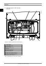
Illustration 5.3 Auxiliary Interfaces
Technical Data
L00410644-01_2q / Rev. date: 2014-06-02
35
5
5

