Sleipner SE IP 60 Скачать руководство пользователя страница 17

 17

4354

13

2022

-

SEP IP 60

Motor Installation

1.  Insert the drive pin to the motor drive shaft. Insert the coupling to align with the drive pin in the motor shaft.

2.  Install the motor onto the motor bracket ensuring the couplings are engaged together correctly (top and bottom). 

(NB: The motor can be placed 

in all directions on the motor bracket. However, ensure the cable terminals are accessible for electrical installation later.)   

3.  If you are installing the motor at an angle of more than 30 degrees off vertical, the motor will require separate/ additional support. 

(NB: Do not 

position supports on the motors top cap.)  

4.  Fasten the bolts holding the motor to the motor bracket with the above torque. 

5.  Check the drive shafts are engaged by rotating the propeller. 

(NB: Rotating the propellers can be hard due to the gear reduction and the motor, 

however the propeller must be able to rotate via hand power.)

MC_0043

!

 Please refer to the graphic for special considerations relating to your model 

!

IMPORTANT 

The thruster motor assembly must be protected using suitable covering to avoid dust/debris ingress from fabrication/maintenance/shipbuilding 

operations. On completion of operations, the cover must be removed before operating the thruster.

MG_0069

1

2

3

4

FASTEN

(18 Nm)

(13.28 lb/ft)

Drive Pin

Gasket

Turn gear leg shaft so 

the motor coupling 

fits into the slots.

Coupling

Motor support

> 30°

MC_0035

Electrical Installation

WARNING

After all electrical connections have been completed, turn off main switch and check the following with an ohmmeter:

1. There is no electrical connection between electro-motor flange and the positive terminal on the motor.

2. There is no electrical connection between electro-motor flange and the negative terminal on the motor.

If unsure contact skilled personnel.

1.   Plan the location of electrical components before starting with the electrical installation. Main electrical components will typically consist of 

battery, Automatic Main Switch (AMS) or manual main switch, Proportional Power Controller (PPC) and motor, see Wiring Diagram chapter for an 

overview. 

2.   Estimate the total length of the power cables to determine the recommended cross section. The total power cable length is defi ned as 

the distances from the positive battery pole, via fuse, main switch and PPC to the motor and all the way back to the negative battery pole. 

Compromising the cable sections named B+, M- and B- on the drawing in the Wiring Diagram chapter.

3.   Find the recommended power cable cross section for you installation by using the estimated total power cable length and the table shown in 

Electrical Reference Guide

 chapter 

4.   Find the recommended fuse size by using the table shown in 

Electrical Reference Guide

 chapter. Use slow blow rated fuses to hold stated nominal 

current for minimum 5 minutes.

5.   Use appropriate dimensioned battery with Cold Cranking Amps (CCA) according to recommendations in 

Electrical Reference Guide

 chapter. 

Battery voltage must be compliant with the voltage rating of the thruster motor and control circuitry. Capacity and rated discharge current of 

battery should be according to rated nominal current drawn and typical duty cycle for thruster operation. Nominal current drawn is listed in the 

Cross Section Guide for Power Cables chapter. The actual voltage at the motor while running the thruster determines the motor RPM and thrust. 

Use larger cable cross section and high-capacity battery for improved performance. 

6.   Install the cable from the as described in chapter Installation of Actuator Cable.

7.   Install the PPC according to instructions in PPC Installation chapter.

8.   Install and connect the battery, fuse, main switch and wiring according to instructions in Wiring Diagram chapter. For safety reasons it is always 

recommended to install a fuse and a main switch on the power cables and as close as possible to the positive battery pole connection. The main 

switch must be installed such that it is easily accessible to disconnect the thruster when not on-board or in the case of an emergency.

Follow the instructions in the Motor Lug Connection chapter when fastening the power cables to the motor.

Sleipner offers both manual main switches and Automatic Main Switches (AMS). Sleipner AMS is controlled by the control panel in addition to the 

option of manual operation. Turning on the control panel does also turn on the automatic main switch. When the control panel is turned off the 

automatic main switch is also turned off. This ensures that the control electronics and motor is only energized when the control panel is turned on. 

Sleipner offers AMS supporting either S-Link or ON/OFF control panels. Ensure to select a main switch with voltage rating according to the chosen 

motor- and battery-voltage. Note that the AMS requires separate power supply which should be protected by a dedicated fuse.

MG_0535

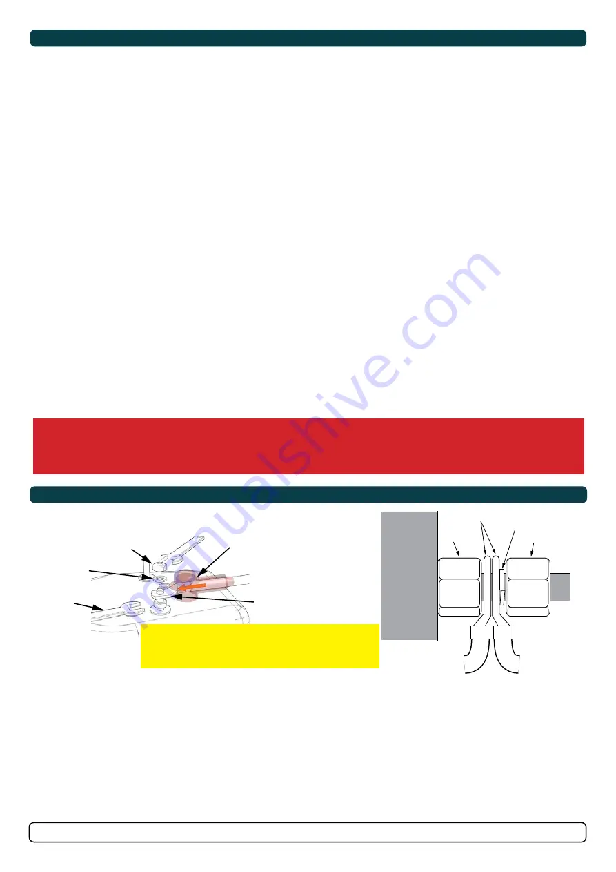
Product Lug Connection Configuration

Nut

Tighten to 

18Nm/ 13.8lb/ft

washers

Isolation Cap

Lugs

Hold in place for 

securing the end nut.

Multi-lug 

configuration

Ensure lug faces 

are back to back.

Spring 

washer

Nut

Nut

Lugs

IMPORTANT

Do NOT use washers between lugs, this causes overheating 

and fire. Spring washers must be placed in the outer 

position before tightening nut.

Содержание SE IP 60

Страница 1: ...IPNER MOTOR AS P O Box 519 N 1612 Fredrikstad Norway www sleipnergroup com DOCUMENT ID REVISION DATE LANGUAGE Installation Guide For Pro Ignition Protected DC Thruster Models SEP IP60 EN I M 4354 13 2...

Страница 2: ...tions 5 Positioning of the tunnel thruster 6 Tunnel Length 7 Tunnel installation in sail boats 8 Water Deflection 9 Tunnel ends 10 Tunnel installation 11 12 Stern tunnel installation 13 Gear Leg Motor...

Страница 3: ...partments must be separated from the thruster to prevent nearby items becoming dusty dirty NB IP version motors generate dust but are enclosed MC_0425 For thruster systems Do not install the thruster...

Страница 4: ...er Depth 185 7 28 185 7 28 TL Minimum tunnel length 128 5 04 128 5 04 TL recommended Recommended tunnel length 165 6 50 165 6 50 T min Minimum tunnel wall thickness 4 0 16 4 0 16 T max Maximum tunnel...

Страница 5: ...4V Power kw Hp Weight kg lbs Maximum Operation Time SE 60 12V 73 kg 161 lbs 60 kg 132 lbs 3 1kw 4hp 16kg 35lbs S2 motor at 2 3 min Duty cycle at 20 c Ambient temperature 24V 73 kg 161 lbs 60 kg 132 lb...

Страница 6: ...eep as possible under the waterline 2 Deeper installations prevent air from being sucked into the tunnel from the surface resulting in reduced thrust performance and increase noise levels during opera...

Страница 7: ...of the tunnel walls to vary in length excessively EG The top tunnel wall is x 4 longer than the bottom wall 2 If the tunnel is too long the friction inside will reduce the water speed and thereby the...

Страница 8: ...fit the tunnel halfway into the underneath section of the existing hull Strengthen it with a deflector spoiler directing the water flow around the tunnel This will allow installation of the thruster i...

Страница 9: ...l entry The depth and shape of this recess will depend on the boat and the angle facing up down aft of the tunnel insert Normally it is angled slightly down because of the water flow on this area 3 Ma...

Страница 10: ...l and thereby reduces the effective tunnel diameter and thrust Turbulence cavitation on the propeller will lessen the thrusters performance and create excess noise 2 For steel aluminium hulls angled t...

Страница 11: ...he back face 5 Cut the tunnel ends to the desired shape and lightly sand its surface Clean the area with acetone or similar where you are going to apply fibreglass NB Do not cast or add breglass to th...

Страница 12: ...installed and cast 1 Round the edges with a radius of 10 of the tunnel diameter 2 For steel aluminium hulls make a slope with a length of 10 15 of the tunnel diameter NB If this is not possible round...

Страница 13: ...l in your Sleipner product delivery Stern Thruster SLEIPNER AS P O Box 519 N 1612 Fredrikstad Norway www sleipnergroup com DOCUMENT ID REVISION DATE LANGUAGE Installation Guide For DC Electric Thruste...

Страница 14: ...the propeller on the gear leg to ensure it is centred and rotates freely with the same clearance from each blade to the tunnel wall Place top motor bracket to measure the drive shaft has come through...

Страница 15: ...er to the end of the shaft spline Tighten with the propeller lock nut 3 Apply anti fouling to the gear leg and propeller Do not apply anti fouling to any rubber elements of the gear leg or anodes MC_0...

Страница 16: ...s on the motors top cap 4 Fasten the bolts holding the motor to the motor bracket with the above torque 5 Check the drive shafts are engaged by rotating the propeller NB Rotating the propellers can be...

Страница 17: ...Nominal current drawn is listed in the Cross Section Guide for Power Cables chapter The actual voltage at the motor while running the thruster determines the motor RPM and thrust Use larger cable cros...

Страница 18: ...A NA AWG 2 0 2 0 4 0 2 x 2 0 2 x 3 0 2 x 3 0 2 x 4 0 2 x 4 0 2 x 4 0 24V 280 A DIN 300 SAE 570 EN 520 ANL 250 mm 35 35 35 50 50 70 70 95 95 120 120 2 x 95 AWG 2 2 2 1 0 1 0 2 0 2 0 3 0 3 0 4 0 4 0 2 x...

Страница 19: ...detailed installation instructions See S Link System Description chapter for detailed information on installation of S Link Power cable and additional S Link components Selection of battery fuse main...

Страница 20: ...e connected to 12VDC or 24VDC To reduce the risk of interference avoid routing the S Link cables close to equipment such as radio transmitters antennas or high voltage cables The backbone must be term...

Страница 21: ...ol Panel installation please refer to the Installation Guide accompanying the control panel to be installed MC_0398 Control Panel SLEIPNER MOTOR AS P O Box 519 N 1612 Fredrikstad Norway www sleipnergr...

Страница 22: ...ouse and propeller but NOT anodes sealing rubber fittings or propeller shafts Propeller is fastened correctly to the shaft Propeller turns freely in tunnel The anode and or holding screw is tightened...

Страница 23: ...s of the defect to the best of the Claimant s knowledge including product identification and serial nbr the date and place of purchase and the name and address of the installer Proof of purchase date...

Страница 24: ...curacies or omissions it may contain Continuous product improvement may change the product specifications without notice Therefore Sleipner Group cannot accept liability for any possible differences b...

Отзывы: