Issue 8 Page 39 of 286
5. Filter Systems
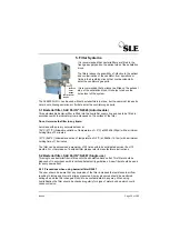
It is recommended that bacteria filters are fitted in the
fresh gas supply and on the patient side of the exhalation
block.
The filters reduce the possibility of infection to the patient
and contamination of the ventilator from secretions or
fluids in the breathing circuits that could accidentally
enter the ventilators gas ports.
It is recommended that a silencer be fitted on the exhaust
side of the exhalation block, this helps to reduce the
noise level of the system.
The SLE2000 HFO+ can be used without bacterial filters in place, but the user must take extra
care in not allowing secretions or fluids to enter the ventilators gas ports.
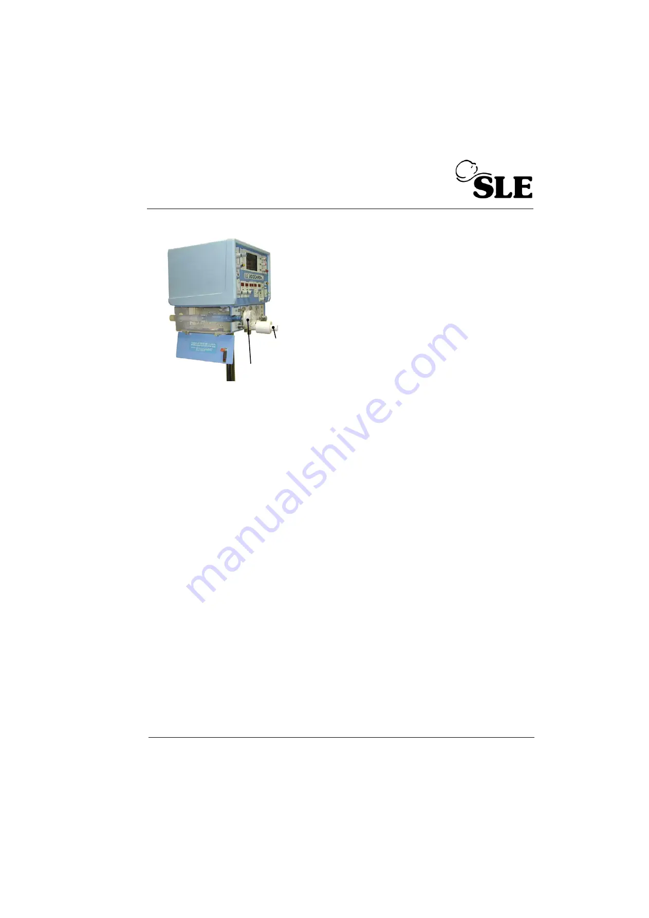
5.1 Bacterial filter, SLE Part Nº:N2029 (Autoclavable)
This autoclavable
bacterial filter is fitted into the humidifier supply line and has to be fitted in
accordance with the indicator arrow embossed on the surface of the filter.
Do not immerse the filter in any liquid.
Autoclave with pure dry saturated steam at:
134ºC (277ºF) (Allowable variation of temperature of +3ºC) at 220kPa (32psi) with a minimum
holding time of 3 minutes
or
121ºC (248ºF) (Allowable variation of temperature of +3ºC) at 96kPa (14.1psi) with a minimum
holding time of 15 minutes.
The filter can be autocalved a maximum of 25 times within its anticipated service life of 12
months. For other makes of
bacterial filter please refer to manufacturers instructions.
5.2 Bacterial filter, SLE Part Nº:N2587 (Single use)
This single use bacterial filter is fitted onto the exhalation block outlet. This filter should be
disposed of in accordance with local hospital authority guidelines. A new filter should be used
for every new patient.
5.2.1 Precautions when using bacterial filter N2587
The user should be aware that any occlusion of the filter increases the resistance to airflow,
resulting in increased or erratic airway pressures. Airway pressures should be monitored
during use and the filter changed if found to be contaminated in any way. When using
humidification the filter should be checked regularly for signs of water build up which could
cause occlusion.
Bacteria Filter
Bacteria
Filter
N2029
N2587
Содержание 2000 HFO+
Страница 1: ...Issue 8 SLE 2000 HFO Ventilator Service manual High Frequency Oscillatory Ventilator ...
Страница 8: ...Page 8 of 286 Issue 8 This page is intentionally blank ...
Страница 9: ...Issue 8 Page 9 of 286 Introduction ...
Страница 11: ...Issue 8 Page 11 of 286 Ventilator Control Description ...
Страница 15: ...Issue 8 Page 15 of 286 2 3 Side panel 1 Fixed jet 2 Rotating jet Note Exhalation block removed 2 1 ...
Страница 20: ...Page 20 of 286 Issue 8 This page is intentionally blank ...
Страница 21: ...Issue 8 Page 21 of 286 Access to Internal Components ...
Страница 34: ...Page 34 of 286 Issue 8 This page is intentionally blank ...
Страница 35: ...Issue 8 Page 35 of 286 Maintenance ...
Страница 43: ...Issue 8 Page 43 of 286 Overhual ...
Страница 45: ...Issue 8 Page 45 of 286 Exchanging a Pneumatic Unit ...
Страница 47: ...Issue 8 Page 47 of 286 Setup and Calibration ...
Страница 74: ...Page 74 of 286 Issue 8 This page is intentionally blank ...
Страница 75: ...Issue 8 Page 75 of 286 Troubleshooting Chart ...
Страница 80: ...Page 80 of 286 Issue 8 This page is intentionally blank ...
Страница 81: ...Issue 8 Page 81 of 286 Technical Specification ...
Страница 98: ...Page 98 of 286 Issue 8 This page is intentionally blank ...
Страница 99: ...Issue 8 Page 99 of 286 Circuit Details ...
Страница 100: ...Page 100 of 286 Issue 8 15 Circuit Details 15 1 A0700 03 Display Board Assembly ...
Страница 101: ...Issue 8 Page 101 of 286 15 1 1 CD A0700 03 Display Board Circuit Diagram ...
Страница 103: ...Issue 8 Page 103 of 286 15 2 A0701 02 LED PCB Assembly ...
Страница 104: ...Page 104 of 286 Issue 8 15 2 1 CD A0701 02 LED Board Circuit Diagram ...
Страница 107: ...Issue 8 Page 107 of 286 15 3 AS A0702 05 CPU PCB Issue 2 Sheet 1 of 2 ...
Страница 108: ...Page 108 of 286 Issue 8 15 3 1 AS A0702 05 Issue 2 Sheet 2 of 2 ...
Страница 114: ...Page 114 of 286 Issue 8 15 4 AS A0702 05 CPU PCB Issue 3 Sheet 1 of 2 ...
Страница 115: ...Issue 8 Page 115 of 286 15 4 1 AS A0702 05 CPU PCB Sheet 2 of 2 ...
Страница 121: ...Issue 8 Page 121 of 286 15 5 AS A0702 05 CPU PCB Issue 3 Sheet 1 of 2 See detail A ...
Страница 122: ...Page 122 of 286 Issue 8 15 5 1 Ventilator CPU Board Detail A C0481 R0658 Link Cut track ...
Страница 129: ...Issue 8 Page 129 of 286 15 6 AS A0736 04 Main PCB Revision E Issue 1 ...
Страница 134: ...Page 134 of 286 Issue 8 15 7 AS A0736 04 Main PCB Revision F Issue 2 Note Check the revision status of the main board ...
Страница 150: ...Page 150 of 286 Issue 8 15 10 AS A0739 02 Motor Drive PCB Issue 1 Sheet 1 Revision B ...
Страница 151: ...Issue 8 Page 151 of 286 15 10 1 AS A0739 02 Motor Drive PCB Issue 1 Sheet 2 Revision B ...
Страница 152: ...Page 152 of 286 Issue 8 15 10 2 CD A0739 03 Motor Drive PCB Circuit Diagram Issue 1 Revision B ...
Страница 155: ...Issue 8 Page 155 of 286 15 11 AS A0739 02 Motor Drive PCB Issue 2 Revision C ...
Страница 156: ...Page 156 of 286 Issue 8 15 11 1 CD A0739 03 Motor Drive PCB Circuit Diagram Issue 3 Revision C ...
Страница 159: ...Issue 8 Page 159 of 286 15 12 AS A0756 HFO Start up Motor PCB Issue 1 ...
Страница 161: ...Issue 8 Page 161 of 286 15 13 AS A0738 02 Alarm PCB Assembly ...
Страница 162: ...Page 162 of 286 Issue 8 15 13 1 CD A0738 02 Alarm PCB Circuit Diagram ...
Страница 165: ...Issue 8 Page 165 of 286 15 14 A0745 01 Pressure Drift Monitor Board ...
Страница 166: ...Page 166 of 286 Issue 8 15 14 1 CD A0745 Pressure Drift Board Circuit Diagram ...
Страница 168: ...Page 168 of 286 Issue 8 15 15 A0746 Flow Trigger PCB ...
Страница 171: ...Issue 8 Page 171 of 286 15 16 CD W0317 Wireloom Issue 2 A3 version on page 225 of circuit diagram appendix ...
Страница 172: ...Page 172 of 286 Issue 8 15 17 CD W0317 Wireloom Issue 3 A3 version on page 227 of circuit diagram appendix ...
Страница 173: ...Issue 8 Page 173 of 286 15 18 CD W0317 Wireloom Issue 4 A3 version on page 229 of circuit diagram appendix ...
Страница 174: ...Page 174 of 286 Issue 8 15 19 Front Panel ...
Страница 175: ...Issue 8 Page 175 of 286 15 20 SK0057 Power Supply Wiring Diagram ...
Страница 176: ...Page 176 of 286 Issue 8 15 21 CD W0307 Electronic Pneumatic Module interconnection ...
Страница 177: ...Issue 8 Page 177 of 286 15 22 Electronic Chassis S RZ 2000 HFO ...
Страница 178: ...Page 178 of 286 Issue 8 ...
Страница 183: ...Issue 8 Page 183 of 286 15 23 2 AS L0263 Sheet 2 of 4 For ventilator with SLE part Nº N2524 60 motor assembly ...
Страница 184: ...Page 184 of 286 Issue 8 15 23 3 AS L0263 Sheet 3 of 4 For ventilator with SLE part Nº N2524 60 motor assembly ...
Страница 185: ...Issue 8 Page 185 of 286 15 23 4 AS L0263 Sheet 4 of 4 For ventilator with SLE part Nº N2524 60 motor assembly ...
Страница 191: ...Issue 8 Page 191 of 286 15 23 5 AS L0263 Sheet 1 of 4 Issue 2 For ventilator with SLE part Nº N2524 61 motor assembly ...
Страница 192: ...Page 192 of 286 Issue 8 15 23 6 AS L0263 Sheet 2 of 4 For ventilator with SLE part Nº N2524 61 motor assembly ...
Страница 193: ...Issue 8 Page 193 of 286 15 23 7 AS L0263 Sheet 3 of 4 For ventilator with SLE part Nº N2524 61 motor assembly ...
Страница 200: ...Page 200 of 286 Issue 8 15 23 9 AS L0263 Sheet 1 of 4 Issue 3 For pneumatic unit with HFO NEEP ...
Страница 201: ...Issue 8 Page 201 of 286 15 23 10 AS L0263 Sheet 2 of 4 For ventilator with SLE part Nº N2524 61 motor assembly ...
Страница 202: ...Page 202 of 286 Issue 8 15 23 11 AS L0263 Sheet 3 of 4 For ventilator with SLE part Nº N2524 61 motor assembly ...
Страница 203: ...Issue 8 Page 203 of 286 15 23 12 AS L0263 Sheet 4 of 4 For ventilator with SLE part Nº N2524 61 motor assembly ...
Страница 209: ...Issue 8 Page 209 of 286 16 A3 Circuit Diagram Appendix A3 circuit Diagram Appendix ...
Страница 210: ...Page 210 of 286 Issue 8 This page is intentionally blank ...
Страница 211: ...Issue 8 Page 211 of 286 CD A0702 05 Issue 2 ...
Страница 212: ...Page 212 of 284 ...
Страница 213: ...Issue 8 Page 213 of 286 CD A0702 05 Issue 3 ...
Страница 214: ...Page 214 of 284 ...
Страница 215: ...Issue 8 Page 215 of 286 CD A0702 05 Issue 4 ...
Страница 216: ...Page 216 of 284 ...
Страница 217: ...Issue 8 Page 217 of 286 Main PCB Circuit Diagram For Rev E Board This section of board is not used ...
Страница 218: ...Page 218 of 284 ...
Страница 219: ...Issue 8 Page 219 of 286 Main PCB Circuit Diagram For Rev F Board Issue 2 This section of board is not used ...
Страница 220: ...Page 220 of 284 ...
Страница 221: ...Issue 8 Page 221 of 286 Main PCB Circuit Diagram For Rev F Board Issue 3 This section of board is not used ...
Страница 222: ...Page 222 of 284 ...
Страница 223: ...Issue 8 Page 223 of 286 Main PCB Circuit Diagram For Rev F Board Issue 4 This section of board is not used ...
Страница 224: ...Page 224 of 284 ...
Страница 225: ...Issue 8 Page 225 of 286 CD W0317 Issue 2 Wireloom Diagram ...
Страница 226: ...Page 226 of 284 ...
Страница 227: ...Issue 8 Page 227 of 286 CD W0317 Issue 3 Wireloom Diagram ...
Страница 228: ...Page 228 of 284 ...
Страница 229: ...Issue 8 Page 229 of 286 CD W0317 Issue 4 Wireloom Diagram ...
Страница 230: ...Page 230 of 284 ...
Страница 231: ...Issue 8 Page 231 of 286 Service Information and Technical Bulletins ...
Страница 240: ...Page 240 of 286 Issue 8 Figure 1 Figure 2 U14 U18 U7 Solder to PCB at these points Figure 3 ...
Страница 241: ...Issue 8 Page 241 of 286 Figure 4b ...
Страница 247: ...Issue 8 Page 247 of 286 100nf ...
Страница 262: ...Page 262 of 286 Issue 8 Pneumatic Schematic ...
Страница 284: ...Page 284 of 286 Issue 8 This page is intentionally blank ...
Страница 286: ......


