Issue 10 (01/10/2004) Page 159 of 258
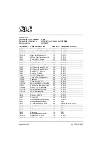
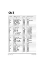
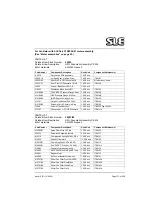
A0737/01
Bargraph Display Pcb Assembly
1.00
ITEM 17
A0738/02
ALARM PCB ASSEMBLY
1.00
ITEM 18
L0015
Graphic LCD Module Assy'
1.00
ITEM 19
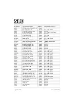
V0226
10K Pot. Panel mt, Single turn
4.00
VR1,VR2,VR3 & VR4
V0416
10K Pot. Wirewound 3590S-2-103
2.00
VR5 & VR6
V0429
1K Potentiometer,cermet
1.00
VR7
V0421
500R Potentiometer, cermet
1.00
F02
N2147
Hour Meter for SLE2000
1.00
ITEM 37
P0234
Mains Filter
1.00
FL1
T0680
Overlay front panel HFO
1.00
ITEM 38
T0209
Knurled Thumb Nut Nylon 66
21.00
ITEM 39
M0294
Mains Terminal Block
1.00
ITEM 40
D0704
Varistor attached to Item 40
1.00
T0934
Terminal Cover
1.00
ITEM 41
P0211/01
Shroud for P0234
1.00
ITEM 42
S0401
25 way D connector socket
1.00
P0025
Mains Plug 13 Amp 3Pin
1.00
M0675
Terminal Receptacle 250
2.00
M0675/01
Boot Receptacle 250
2.00
P0211/01
Shroud for P0234
3.00
ITEM 42
M0677
Power supply NFS110-7902P
1.00
PSU
M0677/01
Cover for psu M0677
1.00
P0025/03
3 amp Mains Fuse
1.00
M0712
PCB Guide 101.6mm long
6.00 Pk 10
M0712/01
PCB Guide 152.4 mm long
6.00 Pk 10
T0942
Window (HFO) EMC
1.00
T0704
Tubing holder
1.00
T0705
Cover (dampener assy)
1.00
T0706
Spacer (dampener assy)
2.00
T0707
Retaining disc (dampener assy)
2.00
N2520
Y Piece hose connector YS4
1.00
N2519
Tubing OD 3mm ID 2mm trans.
4.00 Metre
W0293
20 Way Ribbon Cable IDC
1.00
ITEM 43
W0294
16way STD IDC Ribbon Cable
2.00
ITEM 44
H9908
M3 x 8 socket cap hd s.st
3.00
D0641
Stackable LED - Red
8.00
LED1-LED8
R0436
1.0K Resistor 1% 0.25W SMA0207
1.00
R0488
150K Resistor 1% 0.25W
1.00
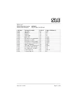
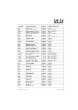
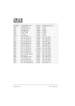
Part Number
Component Description
Used Unit
Component Reference(s)
Содержание 2000 HFO
Страница 1: ...Issue 10 SLE 2000 HFO Ventilator Service manual High Frequency Oscillatory Ventilator 0120 ...
Страница 8: ...Page 8 of 258 Issue 10 01 10 2004 This page is intentionally blank ...
Страница 9: ...Issue 10 01 10 2004 Page 9 of 258 Introduction ...
Страница 11: ...Issue 10 01 10 2004 Page 11 of 258 Ventilator Control Description ...
Страница 17: ...Issue 10 01 10 2004 Page 17 of 258 Access to Internal Components ...
Страница 26: ...Page 26 of 258 Issue 10 01 10 2004 This page is intentionally blank ...
Страница 27: ...Issue 10 01 10 2004 Page 27 of 258 Maintenance ...
Страница 35: ...Issue 10 01 10 2004 Page 35 of 258 Overhual ...
Страница 37: ...Issue 10 01 10 2004 Page 37 of 258 Exchanging a Pneumatic Unit ...
Страница 39: ...Issue 10 01 10 2004 Page 39 of 258 Setup and Calibration ...
Страница 57: ...Issue 10 01 10 2004 Page 57 of 258 Technical Specification ...
Страница 73: ...Issue 10 01 10 2004 Page 73 of 258 Troubleshooting Chart ...
Страница 78: ...Page 78 of 258 Issue 10 01 10 2004 This page is intentionally blank ...
Страница 79: ...Issue 10 01 10 2004 Page 79 of 258 Circuit Details ...
Страница 80: ...Page 80 of 258 Issue 10 01 10 2004 17 Circuit Details 17 1 AS A0700 02 Display Board Assembly ...
Страница 81: ...Issue 10 01 10 2004 Page 81 of 258 17 1 1 CD A0700 02 Display Board Circuit Diagram ...
Страница 83: ...Issue 10 01 10 2004 Page 83 of 258 17 2 AS A0701 02 LED PCB Assembly ...
Страница 84: ...Page 84 of 258 Issue 10 01 10 2004 17 2 1 CD A0701 02 LED Board Circuit Diagram ...
Страница 87: ...Issue 10 01 10 2004 Page 87 of 258 17 3 AS A0702 04 CPU PCB Issue 2 Sheet 1 of 2 ...
Страница 88: ...Page 88 of 258 Issue 10 01 10 2004 17 3 1 AS A0702 04 CPU PCB Issue 1 Sheet 2 of 2 ...
Страница 93: ...Issue 10 01 10 2004 Page 93 of 258 17 4 AS A0702 04 CPU PCB Issue 3 Sheet 1 of 2 ...
Страница 94: ...Page 94 of 258 Issue 10 01 10 2004 17 4 1 AS A0702 04 CPU PCB Issue 3 Sheet 2 of 2 ...
Страница 99: ...Issue 10 01 10 2004 Page 99 of 258 17 5 AS A0702 04 CPU PCB Issue 5 Sheet 1 of 2 ...
Страница 100: ...Page 100 of 258 Issue 10 01 10 2004 17 5 1 AS A0702 04 CPU PCB Issue 5 Sheet 2 of 2 ...
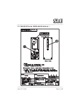
Страница 126: ...Page 126 of 258 Issue 10 01 10 2004 17 10 AS A0737 01 Bargraph Display PCB Assembly ...
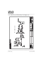
Страница 127: ...Issue 10 01 10 2004 Page 127 of 258 17 10 1 CD A0737 01 Bargraph Display PCB Circuit Diagram ...
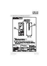
Страница 129: ...Issue 10 01 10 2004 Page 129 of 258 17 11 AS A0738 02 Alarm PCB Assembly ...
Страница 130: ...Page 130 of 258 Issue 10 01 10 2004 17 11 1 CD A0738 02 Alarm PCB Circuit Diagram ...
Страница 134: ...Page 134 of 258 Issue 10 01 10 2004 17 12 AS A0739 02 Motor drive PCB Issue 1 Sheet 1 Revision B ...
Страница 135: ...Issue 10 01 10 2004 Page 135 of 258 17 12 1 AS A0739 02 Motor drive PCB Issue 1 Sheet 2 Revision B ...
Страница 136: ...Page 136 of 258 Issue 10 01 10 2004 17 12 2 CD A0739 02 Motor drive PCB Circuit Diagram Issue 1 Revision B ...
Страница 139: ...Issue 10 01 10 2004 Page 139 of 258 17 13 AS A0739 02 Motor Drive PCB Issue 3 Revision C ...
Страница 140: ...Page 140 of 258 Issue 10 01 10 2004 17 13 1 CD A0739 02 Motor drive PCB Circuit Diagram Issue 3 Revision C ...
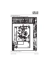
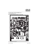
Страница 143: ...Issue 10 01 10 2004 Page 143 of 258 17 14 AS A0756 HFO Motor Start Up PCB Issue 2 ...
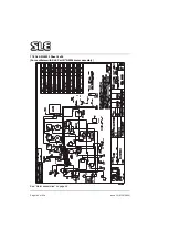
Страница 145: ...Issue 10 01 10 2004 Page 145 of 258 17 15 AS A0745 Pressure Drift Monitor Board Issue 1 ...
Страница 146: ...Page 146 of 258 Issue 10 01 10 2004 17 15 1 CD A0745 Pressure Drift Monitor Board Circuit Diagram Issue 1 ...
Страница 147: ...Issue 10 01 10 2004 Page 147 of 258 17 16 AS A0745 Pressure Drift Monitor Board Issue 2 ...
Страница 148: ...Page 148 of 258 Issue 10 01 10 2004 17 16 1 CD A0745 Pressure Drift Monitor Board Circuit Diagram Issue 5 ...
Страница 150: ...Page 150 of 258 Issue 10 01 10 2004 17 17 Serial Interface Option CD A0702 03 ...
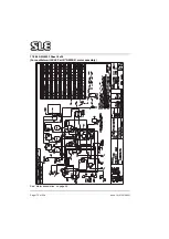
Страница 152: ...Page 152 of 258 Issue 10 01 10 2004 17 18 CD W0308 Wireloom Issue 6 A3 version on page 203 of circuit diagram appendix ...
Страница 153: ...Issue 10 01 10 2004 Page 153 of 258 17 19 Front Panel ...
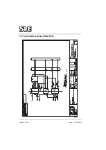
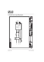
Страница 154: ...Page 154 of 258 Issue 10 01 10 2004 17 20 SK0057 Power Supply Wiring Diagram ...
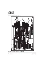
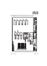
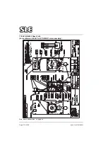
Страница 155: ...Issue 10 01 10 2004 Page 155 of 258 17 21 CD W0307 Electronic Pneumatic Module interconnection ...
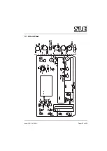
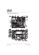
Страница 156: ...Page 156 of 258 Issue 10 01 10 2004 17 22 Electronic Chassis Sheet 1 of 2 ...
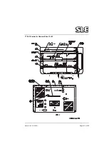
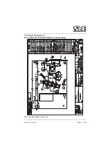
Страница 157: ...Issue 10 01 10 2004 Page 157 of 258 17 22 1 Electronic Chassis Sheet 2 of 2 ...
Страница 186: ...Page 186 of 258 Issue 10 01 10 2004 This page is intentionally blank ...
Страница 187: ...Issue 10 01 10 2004 Page 187 of 258 18 A3 Circuit Diagram Appendix A3 circuit Diagram Appendix ...
Страница 188: ...Page 188 of 258 Issue 10 01 10 2004 The following chapter contains A3 version of the circuit diagrams ...
Страница 189: ...Page 189 of 258 CD A0702 04 Issue 2 ...
Страница 190: ...Page 190 of 258 ...
Страница 191: ...Page 191 of 258 CD A0702 04 Issue 3 ...
Страница 192: ...Page 192 of 258 ...
Страница 193: ...Page 193 of 258 CD A0702 04 Issue 4 ...
Страница 194: ...Page 194 of 258 ...
Страница 195: ...Page 195 of 258 CD A0736 03 Issue 2 Note Please check the revision status of the main board ...
Страница 196: ...Page 196 of 258 ...
Страница 197: ...Page 197 of 258 CD A0736 03 issue 3 Note Please check the revision status of the main board ...
Страница 198: ...Page 198 of 258 ...
Страница 199: ...Page 199 of 258 CD A0736 03 issue 4 Note Please check the revision status of the main board ...
Страница 200: ...Page 200 of 258 ...
Страница 201: ...Page 201 of 258 CD A0736 03 issue 5 Note Please check the revision status of the main board ...
Страница 202: ...Page 202 of 258 ...
Страница 203: ...Page 203 of 258 CD W0308 ...
Страница 204: ...Page 204 of 258 ...
Страница 205: ...Issue 10 01 10 2004 Page 205 of 258 Service Information and Technical Bulletins ...
Страница 212: ...Page 212 of 258 Issue 10 01 10 2004 Circuit diagram before modification Circuit Diagram after modification ...
Страница 221: ...Issue 10 01 10 2004 Page 221 of 258 The pneumatic circuit diagram is shown here ...
Страница 227: ...Issue 10 01 10 2004 Page 227 of 258 F ig u re 1 F ig u re 2 U 1 4 U 1 8 U 7 Solder to PCB at these points Figure 3 ...
Страница 228: ...Page 228 of 258 Issue 10 01 10 2004 Figure 4b ...
Страница 231: ...Issue 10 01 10 2004 Page 231 of 258 ...
Страница 237: ...Issue 10 01 10 2004 Page 237 of 258 100nf ...
Страница 258: ......

