background image


27

 / 

49


5. Setup Instructions 

5.1 Opening 

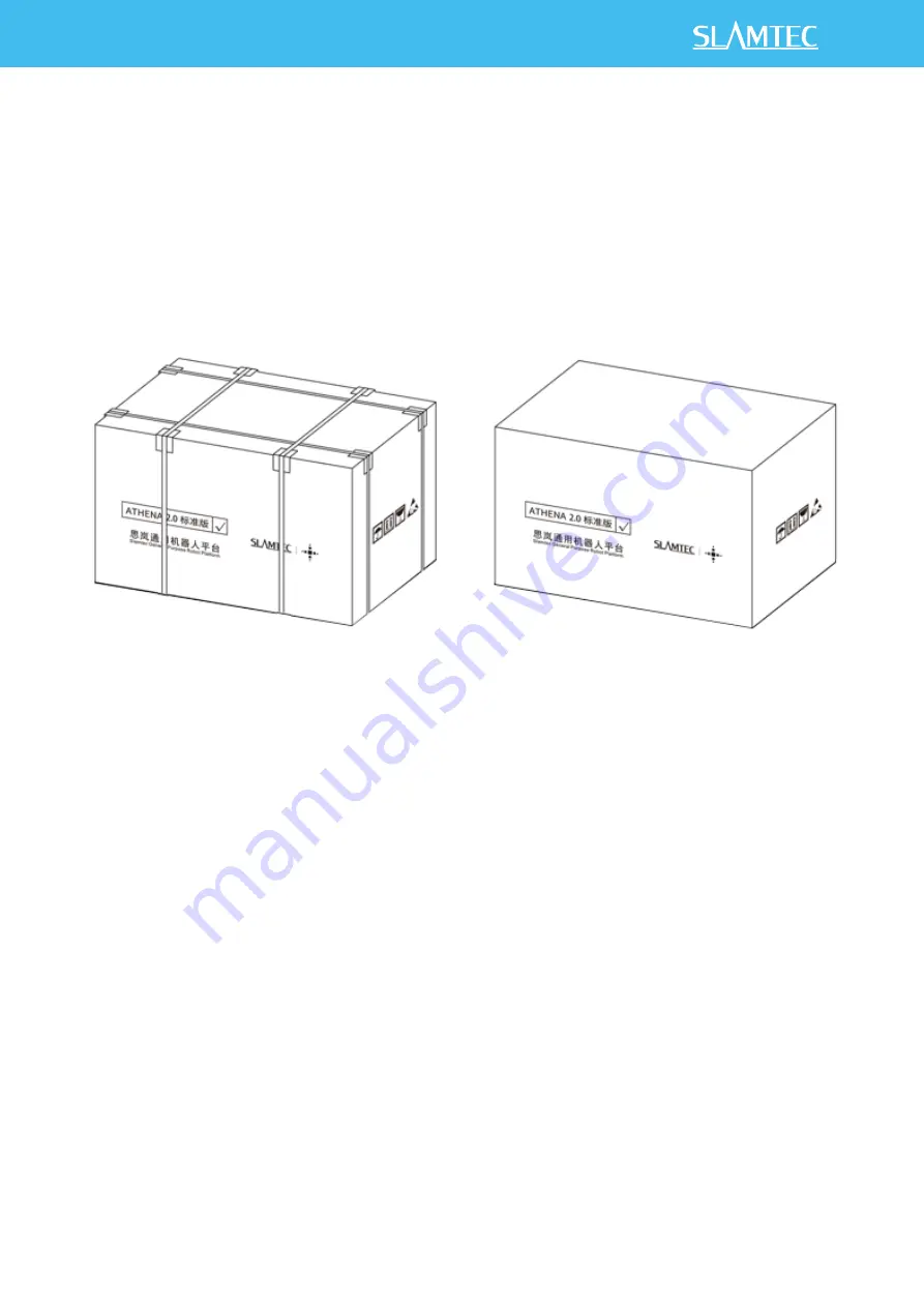
1. After receiving the Athena2.0 machine, please check whether the packing box is intact as shown in 

the left picture, and whether the box on the right side of the Athena2.0 sample of the outer box is checked. 
After confirming that the packing is complete and the box contains Athena2.0, use packing pliers to cut the 
packing tape, remove all packing straps and paper corners, it should be shown as on the right picture. 


5-1 Athena2.0 unpacking 

5.2 Placing Charging Base 

Athena2.0  can  be  charged  by  returning  to  the  charging  base  automatically,  so  the  position  of  the 

charging base will affect the automatic return charging function of Athena2.0. When Athena2.0 returns to 
the charging station, it will generate propelling force. Therefore, it is best to place the charging stand with its 
back against the wall. The wall must meet the following conditions: 

a. The charging base must be attached to the wall, without no obstacle in the middle, try to avoid the 

wall with skirting, etc. 

b. The wall material cannot be high-permeability materials, such as mirror or glass 

c. The wall width needs to be at least three times wider than the width of the charging stand 

d. The wall must be a straight wall, not a curved wall 

The charging base needs to be connected to a 220V power supply. The length of the external power 

cord of the charging base is 1.5m. Therefore, it is necessary to ensure that there is a 220 V interface within 
1.5m  of  the  wall  against  which  the  charging  base  rests.  The  ground  wiring  harness  is  messy  causing 
unnecessary trouble). 

The ground in front of the charging base must meet the following conditions: 

Содержание Athena 2.0

Страница 1: ...form Model N5M42 R2TPL 2022 03 16 rev 1 0 Read through this user manual carefully before use User Manual Small to medium sized robot development Highly adaptable and scalable Powerful optional functio...

Страница 2: ...3 4 REFERENCE OF STRUCTURE DESIGN 24 4 1 INSTALLING INTERFACE OF HOST COMPUTER 24 4 2 INSTRUCTION OF LOAD LIMIT 24 4 3 RADAR CLEARANCE AREA 25 4 4 DEEP CAMERA CLEARANCE AREA 26 5 SETUP INSTRUCTIONS 27...

Страница 3: ...F CODE 38 7 5 DETAILS OF ROBOT API 39 8 INTRODUCTION AND USE OF ELEVATOR CONTROL 42 8 1 INTRODUCTION 42 8 2 FEATURES 42 9 SPECIAL NOTE 44 9 1 CHARGE POINT DEPLOYMENT 44 9 2 RESTRICTED USAGE SCENARIOS...

Страница 4: ...thena 2 0 can implement autonomous mapping localization and navigation by flexibly responding to complex and ever changing operational environments 1 2 Basic Functions 1 2 1 Compact and Flexible Athen...

Страница 5: ...surrounding active environments enabling smart obstacle avoidance and greatly reducing the chances of safety incidents It also has fall resistant and collision resistant protection and emergency stop...

Страница 6: ...5 49 1 3 Exterior...

Страница 7: ...6 49 1 4 Charging Dock Charging dock diagram 1 5 Product List Name Quantity Notes Athena 2 0 body 1 Athena 2 0 chassis body Charging dock 1 Select environment for deployment before use...

Страница 8: ...Field of View FOV H 75 3 V 51 3 Physical magnetic sensor Quantity 2 units Max detection range 3 5 cm Bumper Quantity 2 units Trigger method Physical collision Mapping performance Map resolution 5 cm...

Страница 9: ...ry and capacity Capacity specifications 18 AH standard Battery scalable to 90 AH No load operating time 19h no load Full load operating time 8h full load Charging time 3 4 h standard charging station...

Страница 10: ...9 49 Charging station Size 360 mm 150 mm 320 mm W D H Color White Rated input 100 240V 50 60 Hz 3A Max Rated output DC 25 5V 6A...

Страница 11: ...ust be designed according to rigid regulations If the switch is not designed Athena2 0 will refuse to run Brake When robot is energized press this switch to release the brake and you can push the robo...

Страница 12: ...399 development via USB3 0 to obtain information of code scanning camera Assist precise docking 12V DISP Rated Voltage 12V See the figure below for the design drawings 12V working power of Cube2 to pr...

Страница 13: ...12 49...

Страница 14: ...nual carefully to avoid product damage caused by misoperation 2 The working temperature of the main board is 0 to 40 30 70 RH in order not to damage the product due to excessive cold heat or moisture...

Страница 15: ...e display interfaces are 1 HDMI supporting dual screen display which can meet the needs of flexible and diverse point screen applications The board has a 3 5mm headset socket and a dual channel 5W pow...

Страница 16: ...p 1080i 4k Internet 1 RJ45 Gigabit Ethernet 1 WIFI Bluetooth Audio 1 3 5mm headset socket 1 LINE_MIC audio pin with headset socket Co lay 1 Dual channel 5w 8 power amplifier speaker pin Storage 32GB e...

Страница 17: ...midity 30 70 RH Remark RK3399 is dual core Cortex A72 the highest frequency is 1 8GHz 4 core Cortex A53 the highest frequency is 1 4GHz WIFI specifications 802 1b n g 2 4GHz Bluetooth specifications B...

Страница 18: ...17 49 3 3 3 Introduction of Interfaces 1 Front view of main board 2 Front IO diagram of the main board 3 IO diagram behind the main board 4 Back view of main board...

Страница 19: ...identification method of the first pin on the main board is 1 has a white and bold silkscreen 2 the pins seen on the back of the main board are square holes 3 3 4 Definition of pin function 1 Pin Inte...

Страница 20: ...0 RS232 485 serial port 2 sockets DEBUG PH2 0 4PIN onboard MCU module debugging interface JC2 COM1 RS232 TTL mode setting jumper 3 JC3 COM1 RS232 TTL mode setting jumper 3 JC4 COM2 internal onboard M...

Страница 21: ...and JC5 jointly determine the COM2 signal connection Mode RS232 JCOM2 pin MCU 485A base JC4 JC5 1 2P short interface 2 3 short interface 5 The extension pin contains function key signals such as volu...

Страница 22: ...ND 3 LED_A 4 LED_B Main board and jumper definition continued 1 JP CN pin Signal pin Signal Remark JCOM1 1 RS232_TX 2 RS232_RX 3 GND 4 5V JP CN pin Signal pin Signal Remark JCOM2 1 RS232_TX 485 2 RS23...

Страница 23: ...X 7 GND 8 GND 9 EDP_TX0 10 EDP_TX1 11 EDP_TX0 12 EDP_TX1 13 GND 14 GND 15 EDP_TX2 16 EDP_TX3 17 EDP_TX2 18 EDP_TX3 19 GND 20 GND Main board and jumper definition continued 3 JP CN pin Signal pin Signa...

Страница 24: ...9 9 MIPI_RX_CLK 10 GND 11 MIPI_RX_D2 12 MIPI_RX_D2 13 2 8V 14 MIPI_RST0 15 CIF_PDN1 16 I2C_SDA_CAM 17 I2C_SCL_CAM 18 GND 19 MIPI_RX_D3 20 MIPI_RX_D3 21 MIPI_RX_D0 22 MIPI_RX_D0 23 MIPI_RX_1 24 MIPI_RX...

Страница 25: ...ace of Host Computer As shown in the figure above there are a total of 8 M3 threaded holes for the installation and fixation of the host computer It is recommended to use M3 screws with spring washer...

Страница 26: ...h Slamtec provides the height is 82 mm ii The center of gravity of the whole machine is the overall center of gravity of the chassis plus the robot iii If the center of gravity of the whole machine ex...

Страница 27: ...4 Deep Camera Clearance Area There is a deep camera on the chassis which requires a certain clearance area to avoid being shielded or interfered The host computer cannot exceed the clearance area as s...

Страница 28: ...station it will generate propelling force Therefore it is best to place the charging stand with its back against the wall The wall must meet the following conditions a The charging base must be attach...

Страница 29: ...the wheel hub is in the brake state indicating that the startup is completed If the machine is in the position of charging pile short press the power switch until the power switch indicator lights up...

Страница 30: ...d manually such as pushing it to the charging pile Release the brake button the machine can return to normal working condition and the manual push is blocked 5 6 Connection to Computer Step 1 The hots...

Страница 31: ...tec robostudio run robostudio exe enter the interface of slamtec robostudio enter the IP address and port click connect and RS login succeeds 5 6 Robo studio interface Note The method of IP address qu...

Страница 32: ...nt and log in In the menu toolbar area click File Robot in turn and a docking page named Robot will appear on the left side of the workspace as shown in the figure below The user connects disconnects...

Страница 33: ...uld be set to automatically obtain it using DHCP 5 9 Rob Studio Robot connecting page When finishing connecting the work area will display the robot map information and status information In the robot...

Страница 34: ...entally pushes Athena 2 0 into the virtual wall the Athena 2 0 machine cannot automatically get out of the virtual wall and needs to be pushed out by a human at a random point in RoboStudio The Forbid...

Страница 35: ...ile to Athena2 0 3 4 include iostream 5 include rpos robot_platforms slamware_core_platform h 6 include rpos robot_platforms objects composite_map_reader h 7 include rpos core pose h 9 using namespace...

Страница 36: ...positeMap map Athena2 0_pose 30 set compositemap 31 rpos core Pose home_pose rpos core Pose rpos core Location 0 0 0 32 the home pose in map home_pose should be the home s real pose in new map 33 usin...

Страница 37: ...age supports following functions 1 Check basic information of the device 2 Restart the module 3 Update the firmware Slamtec will regularly provide Athena2 0 firmware updates and upgrades You can easil...

Страница 38: ...App sends instructions to the robot according to various business scenarios and Robot Agent will provide data interfaces task operation interfaces and business services to Robot App 7 1 COMMUNICATION...

Страница 39: ...fore elevator control is part of the function Robot Cloud communicates with the Elevator Agent running on the main control box of the elevator control through the MQTT protocol Its core functions incl...

Страница 40: ...wing is the Robot App calling the Robot Agent interface to make the robot move across floors POST http 127 0 0 1 1448 api core motion v1 actions The request message format is application json 7 5 Deta...

Страница 41: ...segment Get all POI in current map Add POI Empty POI Find POI according to ID Modify POI Delete POI Motion control of the Robot Get all supported actions Get current action Stop current action Create...

Страница 42: ...picking up items End picking up items Get info of objects NOTE delivery business please inform marketing department Restaurant delivery service related interfaces Get the current battery percentage G...

Страница 43: ...ation that robots can only work on the same floor 8 2 2 Intelligence Status Detection Through the built in sensor and adaptive algorithm this product can accurately detect the current floor up and dow...

Страница 44: ...this product can also be easily supported Just install the equipment we specify when installing the device and then turn on the swipe card to bypass it in the APP In this way even if there is a card r...

Страница 45: ...event incorrect recovery after moving 9 2 Restricted usage scenarios Please avoid using Athena2 0 chassis in the following scenarios to avoid chassis failure or damage 1 Overrun heavy transportation D...

Страница 46: ...tery it should be stored in a cool and dry environment 2 For long term storage more than 3 months it is recommended to put it in a dry environment with room temperature of 10 25 and no corrosive gas 3...

Страница 47: ...subsidence of more than 2cm 4 It is recommended to start the equipment on the charging base 5 Do not change the inside of the machine without authorization 6 In environments with many high transmittan...

Страница 48: ...oth when the power is off and ensure that there are no wires paper scraps and other foreign objects stuck on the anti collision bar 2 Maintenance cycle For the maintenance of the main engine it mainly...

Страница 49: ...ition of the charging point has been moved If the position has been moved please contact the after sales department 2 Please confirm whether there is a slope at the position of the charging point If t...

Отзывы: