background image

3

CONTENT

Introduction..........................................................................................................................4

Overview........................................................................................................................4

Installation...........................................................................................................................7

Installing the Console.................................................................................................7
Programming Passwords..........................................................................................9
Phone Number Programming..................................................................................10
Installing Door/Window Sensors.............................................................................12
Installing Motion Sensor...........................................................................................13

Operation..............................................................................................................................15

Alert mode...................................................................................................................15

         Mute....................................................................................................................................16

System Status..............................................................................................................17
Arming The System.....................................................................................................17
Disarming the system...............................................................................................18
Disarming a triggered control panel.....................................................................19
Disarming under Duress..........................................................................................19

          Panic...................................................................................................................................20

System Failure............................................................................................................20

Phone Line Failure............................................................................................20
Sensor Failure.....................................................................................................21
Low Battery...........................................................................................................21

Coummunication.............................................................................................................23

Receiving an emergency call..................................................................................23
Remote Operation by Telephone...........................................................................24
To access the control panel away from home......................................................24

Advanced Programming.................................................................................................26

Zone Dependent Setting – Beep / Alarm..............................................................26
Zone Dependent Setting – Auto Mute....................................................................29
Zone Dependent Setting – Alert Zone (Bypass zone).........................................30
Learn Keychain / Keypad Remotes........................................................................32
Erase Keychain / Keypad Remotes........................................................................33
Learn Sensors..............................................................................................................34
Sensor Location Selection Guide.............................................................................34
Erase Sensors...........................................................................................................36

Home Automation.............................................................................................................37

Learn Control Modules............................................................................................37
Erase Control Modules............................................................................................40
Event Trigger..............................................................................................................42

Trouble Shooting..............................................................................................................44
Accessories......................................................................................................................46
System Configuration.....................................................................................................49
FCC Information................................................................................................................50
CE........................................................................................................................................52

FCC Information

Consumer Information:

a)

This equipment complies with Part 68 of the FCC rules and the require-
ments adopted by the ACTA. On the bottom


of this equipment is a label

that contains, among other information, a product identifier in the format

US:AAAEQ##TXXXX.

 If requested, this number must be provided to the

telephone company.

b)

An applicable certification jacks Universal Service Order Codes (USOC)
for the equipment is provided (i.e., 

RJ11C

) in the packaging with each

piece of approved terminal equipment.

c)

A plug and jack used to connect this equipment to the premises wiring
and telephone network must comply with the applicable FCC Part 68
rules and requirements adopted by the ACTA. A compliant telephone
cord and modular plug is provided with this product. It is designed to be
connected to a compatible modular jack that is also compliant. See
installation instructions for details.

d)

The REN is used to determine the number of devices that may be con-
nected to a telephone line. Excessive RENs on a telephone line may
result in the devices not ringing in response to an incoming call. In most
but not all areas, the sum of RENs should not exceed five (5.0). To be
certain of the number of devices that may be connected to a line, as
determined by the total RENs, contact the local telephone company. [For
products approved after July 23, 2001, the REN for this product is part of
the product identifier that has the format 

US:AAAEQ##TXXXX

. The digits

represented by ## are the REN without a decimal point 

(e.g

., 03 is a

REN of 0.3). For earlier products, the REN is separately shown on the label.]

e)

If this equipment AM-001


causes harm to the telephone network, the

telephone company will notify you in advance that temporary discontinu-
ance of service may be required. But if advance notice isn’t practical, the
telephone company will notify the customer as soon as possible. Also,
you will be advised of your right to file a complaint with the FCC if you
believe it is necessary.

f)   The telephone company may make changes in its facilities, equipment,

operations or procedures that could affect the operation of the equipment.
If this happens the telephone company will provide advance notice in
order for you to make necessary modifications to maintain uninterrupted
service.

50

Содержание AM-100

Страница 1: ... 2005 PATENTED 2005 SKYLINK GROUP Home Smart Center www skylinkhome com CUSTOMER SERVICE 17 Sheard Avenue Brampton Ontario Canada L6Y 1J3 Tel 905 456 8883 Fax 905 456 7819 Email support skylinkhome com MODEL AM 100 TM ...

Страница 2: ...Home Smart Center USER S INSTRUCTIONS English ...

Страница 3: ... 5 Plug the adaptor to the socket outlet that near the equipment and shall be easily accessible SAVE THESE INSTRUCTIONS 1 Declaration of Conformity Application of Council Directive s Radio Equipment and Telecommunication Terminal Equipment Directive 1999 5 EC R TTE Standard s to which Conformity is Declared EMC EN 55022 1998 A1 2000 EN 610000 3 2 2000 EN 61000 3 3 1995 A1 2001 EN 55024 1998 A1 200...

Страница 4: ...an as appropriate The Ringer Equivalence Number is an indication of the maximum number of terminals allowed to be connected to a telephone inter face The termination on an interface may consist of any combination of devices subject only to the requirement that the sum of the Ringer Equivalence Numbers of all the devices does not exceed five g Should you experience trouble with this equipment pleas...

Страница 5: ...used to connect this equipment to the premises wiring and telephone network must comply with the applicable FCC Part 68 rules and requirements adopted by the ACTA A compliant telephone cord and modular plug is provided with this product It is designed to be connected to a compatible modular jack that is also compliant See installation instructions for details d The REN is used to determine the num...

Страница 6: ...s closely you should find it very easy to set up the system In the package you should find the following items One Control Panel One Motion Sensor Two Door Window Sensors One Keychain Remote Alert When Home System Not Armed Beep Beep Alarm Not Home System Armed Alarm Automation Communicator T M AM 001 PS 101 WD 101 4B 101 Master Password ____________________ Secondary Password ____________________...

Страница 7: ...nsors WD 101 5 Install Motion Sensor PS 101 9V Mounting Plate Ball head joint Screws Pack Control Module SW 100 US and Canada To turn home appliances lights on off Max rating 960W Resistive Control Module SW 101U UK SW 101F French SW 101G German 3 models for 3 countries Emergency Dialer AD 433S External dialer with user programmable voice message Calls up to 9 phone numbers One personal voice reco...

Страница 8: ...e detector CO detector so when these detectors are triggered the control panel will be triggered Remote Control 4B 101 Additional keychain remotes for other family members To arm disarm or trigger the panic alarm with this remote Keypad Control KP 434 External keypad control To arm disarm or trigger the the panic alarm with this remote Ideal mounting locations include upper floor backdoor or garag...

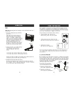
Страница 9: ...atteries the LO BATT LED should be off 3 Connect the phone line from the telephone jack to the back of the control panel where it marks LINE PWR will stay on and PROG LED will stop flashing 4 OPTIONAL If you have another telephone that will be using the same telephone jack you may connect this telephone to PHONE outlet of the the control panel by a phone cord not provided 5 Rotate the antenna to t...

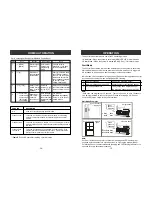
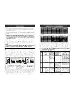
Страница 10: ...times it does and if a motion is then detected that is the First Motion So if you continue to walk in front of the motion sensor it will only pick up the first motion Unless you wait for 20 seconds then walk again the control panel will respond Otherwise the control will only respond to the first motion TROUBLE SHOOTING 45 When a sensor is triggered the Make sure the battery in the sensor is contr...

Страница 11: ...d to disarm the system again by sensor is triggered and the ARM LED either entering the password or disarm by is off keychain remote Although the ARM LED is off but the system is not completely disarmed after an alarm was triggered Refer to page 19 on how to completely disarm a control panel after an alarm has been triggered Why the ARM LED keeps flashing That means you have not programmed any eme...

Страница 12: ...hone memory 1 has higher priority You will hear Enter phone memory You will hear Phone Accepted indicating the phone number and its settings have been programmed successfully Repeat is the number of times that voice emergency message will be played from 1 to 9 times It is recommended to set up the repeat time to 5 or more Redial is the number of times that phone number will be called Each phone nu...

Страница 13: ... how to react to an emergency call The password is treated as a confirmation of the emergency message Once a valid password is entered the control panel will not call that number again it will proceed to the next number If any one of the called parties disarms the control panel the control panel will not continue to dial the remaining phone numbers After calling all the programmed phone numbers th...

Страница 14: ...it is recommended to screw the mounting plate to the frame then apply double sided tape After mounting the sensor if the AAA logo is inverted remove the front cover and rotate it so the AAA logo is in the upright position INSTALLATION Installing Door Window Sensors Transmitter Magnet Double sided foam tape Mounting plate and screws optional Sensor Sensor Sensor Magnet Magnet Red Marking Red Markin...

Страница 15: ...ng a control module which involves 2 parts 1 Erase the memory of the control panel 2 Erase the memory of the control module Part 1 Erase the memory of the Control Panel 1 2 3 PROG MPIN Enter Programming mode Enter master password to programmingmode 3 beeps for valid password 1 long beep for invalid password 0 Select erase control module programming After 0 is entered some zone LEDs will flash or s...

Страница 16: ...etween 2 activations INSTALLATION You may now close the battery cover and re insert the screw Mount the ball head joint on the wall with screws provided Slide the back of the sensor into the ball head joint The mounting angle can be adjusted For outdoor monitoring please refer to page 30 to program the motion sensor to Alert Zone M 0 1 2 3 4 5 6 7 8 9 10 11 12 13 2 4 6 8 10 12 14 DETECTING AREA Un...

Страница 17: ...1 Triggered 2 Beep___Beep___ Beep___Beep Zone 1 Sensor 1 door open Zone 3 Sensor 2 window open Part 1 Learn signal from Control Module to Control Panel HOME AUTOMATION ZONE LED DESCRIPTION Off Zone is not occupied by any control module Flashes once This zone is occupied by another control module Programming another remote to this zone will overwrite the previous control module Flashes twice This z...

Страница 18: ...l can be used to control lights and home applicances with a Control Module Control Module is sold separately Garage door opener can be controlled with a Garage Door Receive sold separately The Control Panel can control up to 5 Control Modules Garage Door Receivers There are 3 ways to control these modules receivers 1 Using the keypad on the control panel to operate these modules receivers manually...

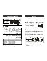
Страница 19: ...us 17 OPERATION OR 1 Press Arm on the control panel or keychain remote 2 Leave the premises within 45 seconds 3 After 45 seconds System will be armed Beep Beep Exit delay 45 seconds 45 seconds later ARM LED on System Armed ADVANCED PROGRAMMING Zone 1 SENSOR 1 Button 1 SENSOR 2 Zone 2 Zone 3 Zone 4 Zone 5 Button 2 Button 3 Button 4 Button 5 Button 6 Button 7 Button 8 Button 9 Button 0 This row Butt...

Страница 20: ...should look something like this Youmayrefertoeach column representing the zone dependent feature to program each zone with the selected feature For example Auto Mute featureis only enabled for zone 3 when you are in the auto mute programming you should enable this feature for zone 3 only the rest of the zones should have this feature disabled Repeat this step for all 4 zone dependent features duri...

Страница 21: ...d and the entry delay beeping will stop the ARM LED will be off ADVANCED PROGRAMMING Learn Sensors You can program up to 10 sensors to the control panel There are 5 zones on the control panel each zone can program up to 2 sensors Before program ming a sensor you must decide which sensor location zone number and sensor number you would like to program the sensor to It is strongly recom mended that ...

Страница 22: ...you should contact your local phone company PANIC ARM DISARM AUX Control other Skylink receiver such as Garage Door Receiver Model 18R ADVANCED PROGRAMMING Erase Keychain Keypad Remotes 1 2 3 PROG MPIN Enter Programming mode Enter master password to pro gramming mode 3 beeps for valid password 1 long beep for invalid password 0 Select erase remote programming After 0 is entered some zone LEDs will...

Страница 23: ...e announcement zone X sensor Y failure will be played ADVANCED PROGRAMMING ZONE LED DESCRIPTION Off Zone is not occupied by any remote Flashes twice This zone is occupied by another remote Programming another remote to this zone will overwrite the previous remote Flashes once This zone is occupied by a control module Optional You can still program a remote to this zone and it will not overwrite th...

Страница 24: ...ensor Y low battery where X and Y represent the zone and sensor number Please replace the battery of that sensor ADVANCED PROGRAMMING To enable alert zone feature follow the instructions below 1 2 3 4 Enter Program ming mode Enter master password to programming mode 3 beeps for valid password 1 long beep for invalid password Refer to the diagram below to select the appropriate setting PROG when fi...

Страница 25: ... the next section Remote Operation by Telephone Zone 1 Sensor 1 Triggered Enter Password Arm Disarm Check status Control lighting etc Disconnect COMMUNICATION 23 Zone 1 DISABLE AUTO MUTE Button 1 ENABLE AUTO MUTE Zone 2 Zone 3 Zone 4 Zone 5 Button 2 Button 3 Button 4 Button 5 Button 6 Button 7 Button 8 Button 9 Button 0 This row Buttons to Disable Auto Mute Zone LED Flash This row Buttons to Enabl...

Страница 26: ...ted either beep or alarm For example if a door is opened the beep will not stop until the door is closed If the door is open for 2 hours the beep will go on for 2 hours There are times that this is not desired With the auto mute feature enabled the beep will go on for only 20 seconds After that even if the sensor remains open the beep will stop only the zone LED will flash to indicate the sensor i...

Страница 27: ... mode Enter master password to programmingmode 3 beeps for valid password 1 long beep for invalid password 5 Select Beep Alarm Setting After 5 is entered some zone LEDs will flash or stay on This indicates whether that zone is set to beep or alarm 3 Set to Beep 1 to 5 SettoAlarm 6 to 0 Select which zone you would like to Beep or Alarm Refer to the diagram below to select the appro priate setting I...

Страница 28: ...f a zone is set to Alarm alarm will sound instantly when a sensor is triggered Alarm will stop when the sensor is deactivated or reaches a 3 minute time out period System Armed Alarm Mode If a zone is set to Beep the control panel will give entry exit delay If a zone is set to Alarm the siren will sound immediately without entry delay Alarm Mode System Armed If a sensor is triggered i e opening a ...

Отзывы: