5. POWER
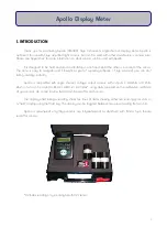
Apollo is powered by a 9V PP3 battery, fitted into a compartment on the back of the meter. One PP3
alkaline battery is shipped with Apollo. Please make sure to insert the battery in the correct orientation (take
notice of the + and — shown on the battery and inside the case.) No damage to Apollo will occur if it is
inserted incorrectly by accident.
A battery is expected to last approximately 24 hours of continuous use at normal working conditions
(~20
o
C), although this may be less if using amplified sensors that require a voltage input. Rechargeable
batteries may be used if preferred, although they will usually not last as long as "normal" batteries, and will
need recharging more often.
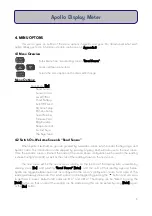
It is possible, and recommended, to check the battery status from the main menu frequently - at least
prior to every use, and if Apollo is used for long periods of time, then perhaps every 2-3 hours. The menu
option shows an actual reading of battery Voltage, as well as a meaningful "status", e.g. good (at >8.1V),
medium (6.9 - 8.1V), low (6.0 - 6.9V) battery. If it is below 6.0V, then a message will apear prompting a battery
change. Apollo's readings will remain accurate until the LCD display fades. These values are based on an
alkaline battery being used.
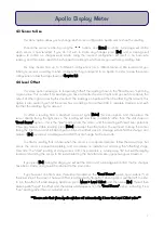
Apollo has an AutoOff function to save battery life. Please see Section 4.6 for more information.
6. SENSOR CONNECTION
Apollo has a 5-pin Binder female socket. All Apollo-compatible Skye sensors are fitted with a matching
plug. To attach a Skye light sensor to Apollo match up the sensor plug to the socket and align the locating
pin. Push together and screw up gently finger tight. This type of connection is waterproof, however the Apollo
meter itself is only splashproof.
The Apollo meter is compatible with single channel voltage output sensors. Skye sensors are wired
thus, but please see individual sensor manual(s) for more information.
Apollo can be configured to work with various 1 channel sensor
types. The following describe the connection modes that can be
changed in the "Wr Sensr Setup" menu. More information can be
found in Appendix 2.
Mode 3
= Differential Floating
Mode 4
= Differential Grounded
Mode 5
= Differential (2.5V referenced)
11
Apollo Display Meter
Pin #
Function
Pin 1
+5V Output
Pin 2
Not Connected
Pin 3
–'ve Voltage Input
Pin 4
+'ve Voltage Input
Pin 5
Analog/ Supply Ground.
Содержание APOLLO SKA 400
Страница 21: ...APPENDIX 3 MENU NAVIGATION TREE 18...


