Page 3 of 4
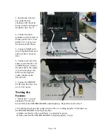
3- Position the CK-1A8
box under the base
telephone with the jacks
facing towards the back of
the phone. (See Fig. 3).
4- Connect the short
modular cord from [1&2 to
Phone] on the CK-1 to the
[LINE 1/L1+L2] jack on
the bottom of the Phone.
5- Connect a MOD cord
from Telephone Wall Jack
1&2 to [1&2 to Line] on
CK-1.
6- Connect one end of the
audio cord to the CK-1A8
AUDIO IN jack. Connect
the other end to the output
of your audio player. Do
NOT use the supplied
Audio Adapter on the
CK1A8 side.
7- Connect the POWER
CUBE from the CK-1 box
to 115VAC power.
Testing the
System:
1- Pickup line 1 on your
telephone. The line one
Green LED on the SENSOR BOARD should light up. Repeat this test for line 2.
2. If both lines light up when picked up, the CK-1 is working properly. If the lights on
the SENSOR BOARD do not light up, then
a) Make sure that the CK-1 and Phone is connected to power.
b) Make sure that the SENSOR BOARD is aligned properly. (Fig 2)
FIG #3
LINE 1/L1+L2
1 & 2 To Phone
Audio Cord from Player
Line 1 & 2 to Wall


