21
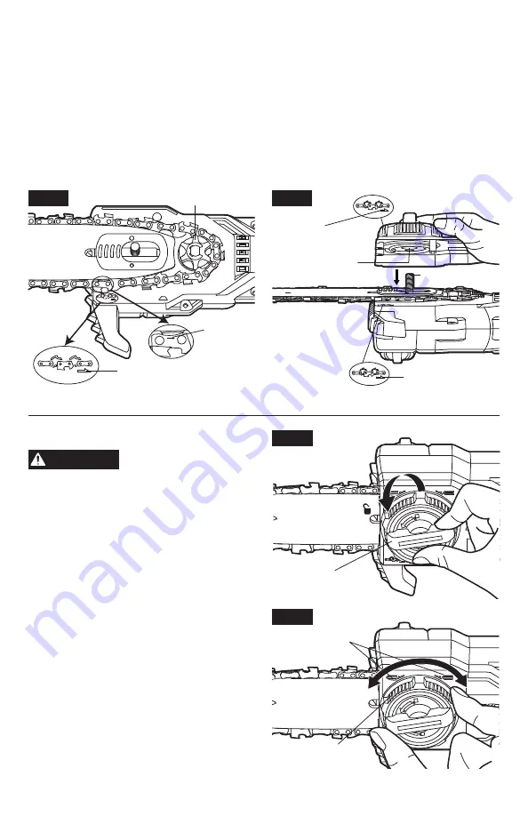
4. Hold the chain in position on the guide bar and place the guide bar and chain, with the bar
metal plate facing up, in the mounting surface of the housing. At the same time guide the
loop around the drive sprocket (Fig. 11c). Make sure that the cutter direction arrows on the
saw chain correspond to the rotation direction arrow on the guide.
5. Attach the side cover to the housing so that the screw hole of the locking knob is aligned
with the locking bolt in the housing (Fig. 11d). At the same time make sure that the
rotation direction arrow on the side cover corresponds to the rotation direction arrow on
the housing. Lightly tighten the locking knob clockwise. The bar must be free to move for
tension adjustment.
Do not fully tighten the locking knob until after you have adjusted the chain tension (see the
following section“Tensioning the saw chain”)
Fig. 11c
Rotation
Direction Arrow
Cutter
Direction
Arrow
Drive Sprocket
Fig. 11d
Rotation
Direction Arrow
Rotation
Direction Arrow
Screw Hole
Locking Bolt
Tensioning the saw chain
CAUTION
The saw chain must be
properly tensioned before
using .
1. Lift up the tip of the guide bar and keep
it slightly lifted as you adjust the tension.
Ensure that the guide bar has some
movement; loosen the locking knob slightly
if necessary.
2. Loosen the locking knob of the side cover a
few turns (Fig. 12a).
3. Adjust the chain tension with the chain-
tension adjusting sleeve according to chain-
tension adjusting mark on the side cover.
Turning the sleeve clockwise increases the
chain tension. Turning it counterclockwise
decreases the chain tension (Fig. 12b).
Fig. 12a
Locking Knob
Fig. 12b
Chain-tension
Adjusting Mark
Chain-tension
adjusting Sleeve


