Sitech GCS900 Скачать руководство пользователя страница 15


Field Reference Guide

SITECH TECHNOLOGY DEALER


GCS900 Verify System Accuracy 

Version: 

13.1 


Verify the system accuracy at the start of each work day using a Permanent Bench Point  
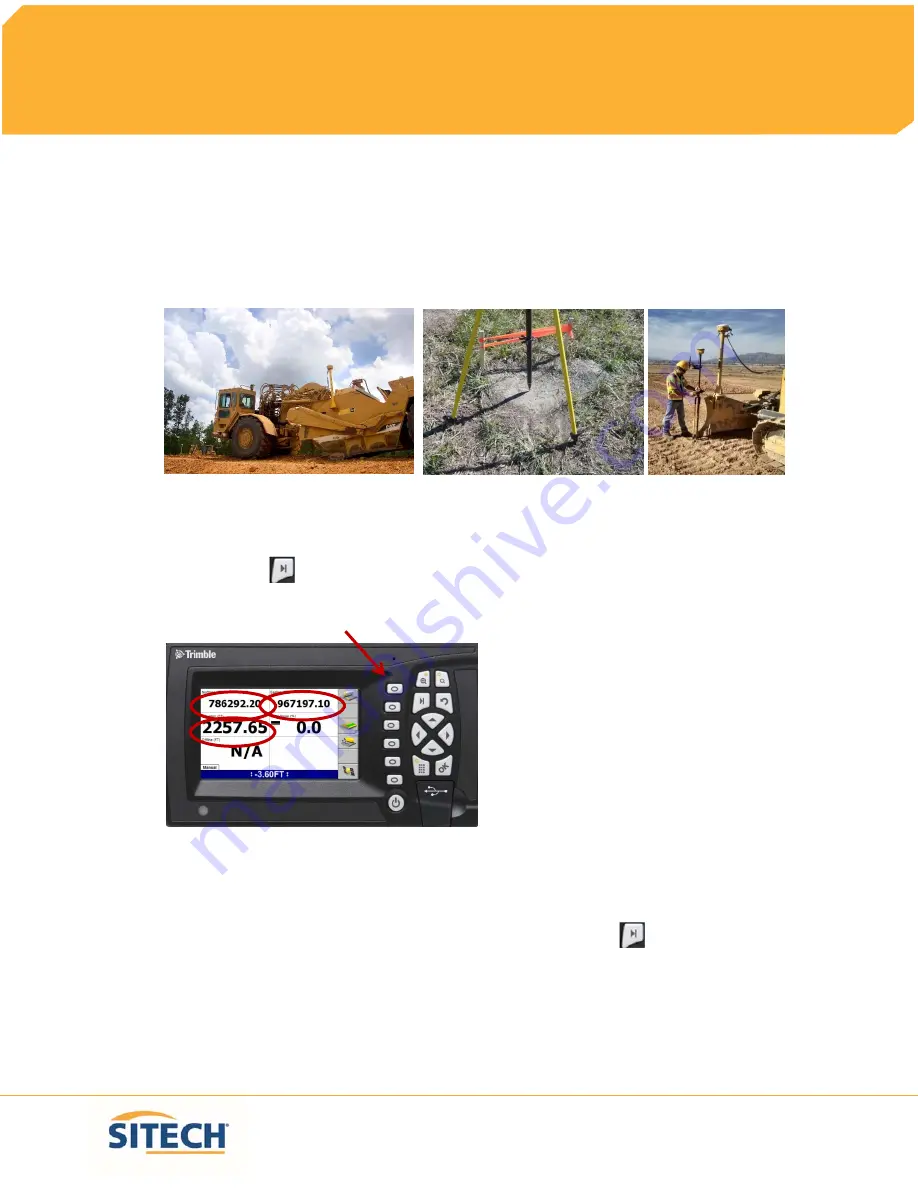


1.


Move machine to 

Bench Point 

with the 

Blade


low to the ground


2.


Position 

Blade Tip

 over 

Bench Point


3.


Press 

“Next” 


until 

Text Screen 2

 is displayed 

4.


Verify correct 

Blade Tip

 is selected Press 

“F1”

 to change 

Blade Tip


5.


Verify 

Northing, Easting

 and 

Elevation

 are correct 

(add distance above Bench Point)


6.


See Supervisor if 

Northing

 and 

Easting

 do not match 

7.


See Supervisor if 

Elevation

 does not match and


Press 

“Next”


Page 8

Содержание GCS900

Страница 1: ...Field Reference Guides GCS900 Scraper Version 13 13 SITECH Rocky Mountain www sitechrockymtn com ...

Страница 2: ......

Страница 3: ... Page CB460 Control Box Layout 3 Scraper Training Display Settings 4 Check Blade Wear 6 Load Design 7 Verify System Accuracy 8 Vertical Offset 9 Horizontal Offset 10 Vertical Guidance 12 Cut and Fill Site Map 13 Lane Guidance 14 Sensor Calibration 15 Connect to Wi Fi 16 TCC Settings 17 Configure Remote Assistant 18 Wireless Data Sync 19 Start Remote Assistant 20 Connect to IBSS Base 21 ...

Страница 4: ......

Страница 5: ...Page CB460 Control Box Layout 3 Scraper Training Display Settings 4 Check Blade Wear 6 Load Design 7 Verify System Accuracy 8 Vertical Offset 9 Horizontal Offset 10 Vertical Guidance 12 Cut and Fill Site Map 13 Lane Guidance 14 Sensor Calibration 15 Connect to Wi Fi 16 TCC Settings 17 Configure Remote Assistant 18 Wireless Data Sync 19 Start Remote Assistant 20 Connect to IBSS Base 21 ...

Страница 6: ......

Страница 7: ...per Training Display Settings 4 Check Blade Wear 6 Load Design 7 Verify System Accuracy 8 Vertical Offset 9 Horizontal Offset 10 Vertical Guidance 12 Cut and Fill Site Map 13 Lane Guidance 14 Sensor Calibration 15 Connect to Wi Fi 16 TCC Settings 17 Configure Remote Assistant 18 Wireless Data Sync 19 Start Remote Assistant 20 Connect to IBSS Base 21 ...

Страница 8: ......

Страница 9: ...Field Reference Guide SITECH TECHNOLOGY DEALER Power Menu USB Port Enter Next Key Escape Go Back Cut Fill Right Function Keys F1 F6 Zoom In Out Cut Fill Left Horizontal Guidance Page 3 ...

Страница 10: ......

Страница 11: ...d overcut to NO and Press OK 8 Select Increment Switch Adjustment and Press OK 9 Change Vertical offset increment 0 00 and Press OK 10 Select Text Items and Press OK 11 Press F1 and Uncheck each Item checked 12 Press F1 to select Cut Fill Left Offline 3D and Cut Fill Right select in order 13 Press F3 Cross Section 14 Press F1 and Uncheck each Item checked 15 Press F1 to select Cut Fill Left Offlin...

Страница 12: ... 2 23 Press F1 and Uncheck each Item checked 24 Press F1 to select Northing 3D Easting 3D Elevation 3D Mainfall and Offline 3D select in order 25 Press OK 26 Select Save Settings and Press OK 27 Select Display Settings and Press OK 28 Enter Operator s Name such as Joe G and Press OK 29 Press ESC twice to return to operating screen Page 5 ...

Страница 13: ...900 Check Blade Wear Version 13 1 1 Press Menu 2 Select Blade Wear and Press OK 3 Measure from Center of Cutting Edge Bolts to Bottom of Blade 4 Do not use Bolt at Blade Tip 5 Enter Distance and Press OK 6 Press ESC to return to operating screen Page 6 ...

Страница 14: ...nce Guide SITECH TECHNOLOGY DEALER GCS900 Load Design Version 13 1 1 Press Menu 2 Select Select Design and Press OK 3 Use Arrows to highlight Design and Press OK 4 Press ESC to return to the operating screen Page 7 ...

Страница 15: ...nch Point with the Blade low to the ground 2 Position Blade Tip over Bench Point 3 Press Next until Text Screen 2 is displayed 4 Verify correct Blade Tip is selected Press F1 to change Blade Tip 5 Verify Northing Easting and Elevation are correct add distance above Bench Point 6 See Supervisor if Northing and Easting do not match 7 See Supervisor if Elevation does not match and Press Next Page 8 ...

Страница 16: ... F4 to enter Horizontal and Vertical Offset 2 Press F6 until Vertical Offset is displayed at the top left of screen 3 Enter Vertical Offset and Press F2 to select above or below Design 4 Press OK to return to operating screen 5 Vertical Offset is displayed at the bottom of the screen Page 9 ...

Страница 17: ... 13 1 1 Press F4 to enter Horizontal and Vertical Offset 2 Press F6 until Horizontal Offset is displayed at the top left of screen 3 Press F1 Alignment 4 Use Arrows to Select Plan Line if list is displayed and Press OK 5 Use Arrows to Select Line Offset and Press F1 Select Page 10 ...

Страница 18: ...r Offset distance 7 Press F2 Select Offset to be Left or Right of the line 3 00 is Left 8 Press OK to return to operating screen 9 Horizontal Offset is highlighted in red 10 Press F1 to change Blade Left or Right Page 11 ...

Страница 19: ... to NO 4 Press F1 for Change Method 5 Select Method from list and Press OK 6 Press OK to accept change 7 Press ESC to return to operating screen 1 One Point Center is the default setting used for long or wide surfaces It also allows for shaping crowns by holding the slope past the crown point One Point Focus is used for narrow surfaces such as shoulders or slopes Page 12 ...

Страница 20: ...to Yes scroll down list 3 Change Blade tip mapping to Automatics on and Press OK 4 Select Main Screen views and Press OK 5 Under Active views select Cut Fill Yes 6 Under Main Screen Softkeys select Softkey 5 Mapping On Off Auto and Press OK 7 Press Esc to Main Screen 8 Press F5 until Mapping only in Automatic is displayed 9 Press Next until Plan View with Cut Fill Scale is displayed Page 13 ...

Страница 21: ...eld Reference Guide SITECH TECHNOLOGY DEALER GCS900 Lane Guidance Version 13 1 1 Move Blade Tip with Focus over Lane to be Extended 2 Press F3 for Lane Guidance 3 F3 turns Lane Guidance Off and ON Page 14 ...

Страница 22: ...GCS900 Dozer Sensor Calibration Version 13 1 1 Press Menu 2 Select Calibrate Sensors and Press OK 3 Select Blade slope sensor turn around and Press OK 4 Following instructions 5 Press F6 Finish 6 Press ESC twice to return to operating screen Page 15 ...

Страница 23: ...2 Press F2 Installation 3 Select Connectivity Settings then press OK 4 Select Wi Fi Network then press OK 5 Press F1 New 6 Select the Wi Fi you wish to connect to press OK 7 Enter Pass Phrase 8 Press F6 9 Press F6 Finish 10 Select the Wi Fi to connect to Press OK 11 Press 2 times to return to main menu Page 16 ...

Страница 24: ...tallation 3 Select Connectivity Settings then press OK 4 Select Connected Community Settings then press OK 5 Enter Device Password then press Next 6 Enter Organization then press Next 7 Filespace and Work Group Folder should be left to default 8 Press OK 9 Press 2 times to return to them main screen Page 17 ...

Страница 25: ...stant GCS900 Version 13 1 1 Press Menu 2 Press F2 Installation 3 Select Connectivity Settings then press OK 4 Select Remote Assistant Configuration then press OK 5 Enter Support Number 6 Press F1 Force Upgrade 7 Press OK 8 Press 2 times to return to main screen Page 18 ...

Страница 26: ...ss Data Sync GCS900 Version 13 1 1 Press Menu 2 Press F2 Installation 3 Select Connectivity Settings then press OK 4 Select Wireless Data Sync then press OK 5 Press F1 Start 6 When synchronization is complete Press ESC 3 times to operating screen Page 19 ...

Страница 27: ...ER Start Remote Assistant GCS900 Version 13 1 1 Press Menu 2 Select Remote Assistant then press OK 3 Press F1 Start 4 Once icon appears at the bottom of the screen the machine is connected 5 Press ESC 2 times to return to them main screen Page 20 ...

Страница 28: ...ect GNSS Base Configuration then press OK 5 Select IBSS Remote Base 6 Press F1 Create New 7 Device Password and Organization should be populated if not see TCC Settings Sheet 8 Press F6 9 Select the Base from list and Press F6 10 Review IBSS Base Name and Press F6 Finish 11 Select IBSS Remote Base 12 Use left or right arrow keys to select correct base name and Press OK 13 Press 2 times to return t...

Страница 29: ...Service and Support www sitechrockymtn com 866 903 2335 Service Center Locations SITECH Rocky Mountain 2420 Uravan Street Aurora Co 80011 ...

Отзывы: