Siskiyou Corporation
MC1100e User's Manual
Siskiyou Corporation
Phone (toll free): 1-877-313-6418
www.siskiyou.com
Phone: 1-541-479-8697
Page 5
Installation:
CAUTION: MAKE SURE ALL CONNECTORS ARE SECURELY PLUGGED IN BEFORE POWER IS
TURNED ON. DO NOT REMOVE CONNECTORS WHILE POWER IS ON. FAILURE TO DO SO
CAN RESULT IN A SHORT CIRCUIT AND PERMANENT DAMAGE TO THE SYSTEM.
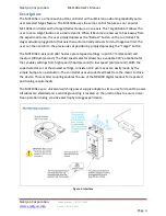
To install the MC1100e, please refer to Figure 1: Interface or the supplied set up
instructions. Supplied with the MC1100e are two ¼-20 screws that can be used to
secure the junction box to the work station. It is also possible to use cable ties (not
included) to mount the junction box.
It is advised to place the controller away from the experiment area. Any liquid that may
come in contact with the controller can cause permanent damage to the system. It is
also advised to add a ground wire onto the junction box and attach the free end of the
wire to a metal surface outside of the system. The lug to use is labeled by the electrical
symbol for “ground”:
Interface:
Junction Box
Power In:
Using the supplied power adapter, the user can connect the power adapter to
the junction box and supply power to the system.
Power Switch:
The power switch turns on the junction box and the controller. This is
required to be on in order to use the MC1100e. Turning off the power switch will cease
all operations with manipulators remaining in place. The same applies to loss of power.
Ground:
By attaching a wire from the ground lug to a metal surface (that is not part of
the experimental system), the users helps prevent damage from static shock and to
ensure noise-free operation while in use. The lug is represented by the electrical symbol
for “ground”:
Controller:
The 25 pin, male connector, is used for connecting the controller to the
junction box.
1, 2, 3, and 4 Ports:
The 25 pin, female connectors, are used for connecting the motor
drive cables to the junction box. A motor drive must be plugged into port 1 for the
MC1100e to work.


