


© 2003 - 2005 Sipura Technology, Inc
Proprietary (See Copyright Notice on Page 2)
20
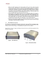
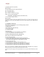
4. One LED for Data Link and Activity (
Figure 3, above):
This LED indicates status via the following behaviors:
ON – LED remains solid on
OFF – LED remains solid off
FAST – 0.125s on, 0.125s off continuously
SLOW – 0.5s on, 0.5s off continuously
Variable Blink – LED blinks according to packet traffic activity
5. One 5 Volt Power Adapter Interface (
Figure 3, above)
This interface accepts the SPA power adapter that came with the unit. Sipura Technology does not
support the use of any other power adapters other then the power adapter that was shipped with the
SPA unit.
2. Installation Overview
Please check to make sure that you have the following package contents:
1. Sipura Phone Adapter Unit
2. Ethernet Cable
3. RJ-11 Phone Cable (SPA-3000 Only)
4. SPA Quickstart Guide
5. 5 Volt Power Adapter
You will also need:
1. One or Two Analog Touch Tone Telephones (or Fax Machine)
2. Access to an IP Network via an Ethernet Connection
3. Access to a PSTN network connection – SPA-3000 only.
Please observe the following steps to install the SPA.
From the Left Side of the SPA:
1. Insert a standard RJ-45 Ethernet cable (included) into the LAN port.
2. Insert the power adapter cable into the 5V power adapter cable receptacle.
Ensure that the power adapter jack is snugly attached to the SPA.
From the Right Side of the SPA:
1. Insert a standard RJ-11 telephone cable into the Phone 1 port.
2. Connect the other end of the cable to an analog telephone or fax machine.
3. Insert a standard RJ-11 telephone cable into the Phone 2 port (Optional).
4. Connect the other end of the cable to an analog telephone or fax machine.
Note: Do not connect RJ-11 telephone cable from the SPA-1000 or SPA-2000 to the wall jack to
prevent any chance of connection to the circuit switched telco network.
You may now insert the plug end of the power adapter into a live power outlet which will power up the
SPA.


