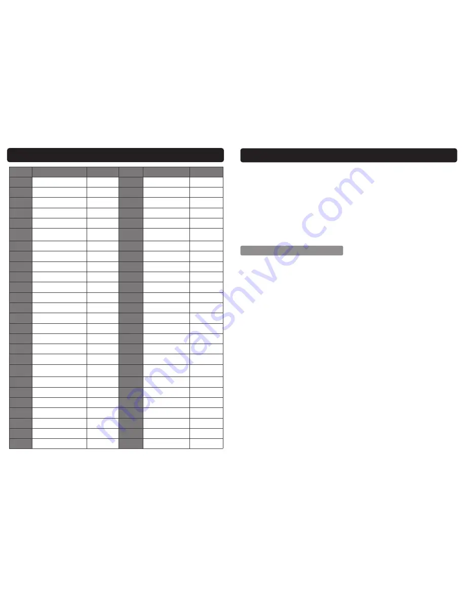
background image

28 

Ref. No. 

Description 

Sip Part No. 

Ref. No. 

Description 

Sip Part No. 

1.  

Support for wire feeder 

WE02-00308 

27. 

Output load small PCB  WE02-00334 

2. 

Top cover 

WE02-00309 

28. 

Output busbar 

WE02-00335 

3. 

Power transformer 

WE02-00310 

29. 

Front panel 

WE02-00336 

4. 

power filter 

WE02-00311 

30. 

Plastic frame surround  WE02-00337 

5. 

Main PCB 

WE02-00312 

31. 

Dinse socket 

WE02-00338 

6. 

Mounting plate 

WE02-00313 

32. 

Wire feed Control 

socket-6 Pin 

WE02-00339 

7. 

3 Phase rectifier bridge 

WE02-00314 

33. 

Potentiometer knob 

WE02-00340 

8.  

Gas bottle retaining chain  WE02-00315 

34. 

Handle 

WE02-00341 

9. 

Mains power cable 

WE02-00316 

35. 

Control panel 

WE02-00342 

10. 

Cable gland 

WE02-00317 

36. 

Output reactor / choke  WE02-00343 

11. 

back pane 

WE02-00318 

37. 

Inductance Filter 

WE02-00344 

12. 

Leakage protection switch  WE02-00319 

38. 

left side panel 

WE02-00345 

13. 

Switch bracket 

WE02-00320 

39. 

Main transformer 

WE02-00346 

14. 

Fan 

WE02-00321 

40. 

Heatshield 

WE02-00347 

15. 

Perspex Insulating Screen  WE02-00322 

41. 

Heatshield insulator 

WE02-00348 

16. 

right-side plate 

WE02-00323 

42. 

IGBT 

WE02-00349 

17. 

Heatsink 

WE02-00324 

43. 

IGBT busbar 

WE02-00350 

18. 

Fast Recovery Diode 

WE02-00325 

44. 

Common inductor 

WE02-00351 

19. 

Output rectifier board 

WE02-00326 

45. 

Wire feed PCB 

WE02-00352 

20. 

Rear wheel - single 

WE02-00327 

46. 

PWM PCB 

WE02-00353 

21. 

Bottle carrier 

WE02-00328 

47. 

Capacitor fixing panel  WE02-00354 

22. 

Heatsink bracket 

WE02-00329 

48. 

Capacitor filter 

WE02-00355 

23. 

Bottom 

WE02-00330 


24. 

Bottom baffle plate 

WE02-00331 


25. 

Swivel Castor wheel 

WE02-00332 


26. 

Heatsink Insulator 

WE02-00333 


  PARTS LIST -  WELDING INVERTER 05776 

  SAFETY INSTRUCTIONS….cont 

 

Ventilation  must be  adequate to remove the smoke  and fumes during  welding 
(see the relevant safety standard for acceptable levels). 

 

Toxic gases may be given off when welding, especially if zinc or cadmium coated 
materials  are  involved,  welding  should  be  carried  out  in  a  well  ventilated  area 
and the operator should always be alert to fume build-up. 

 

Areas with little or no ventilation should always use a fume extractor. 

 

Vapours of chlorinated solvents can form the toxic gas phosgene when exposed 
to  U.V  radiation  from  an  electric  arc.  All  solvents,  degreasers  and  potential 
sources of these vapours must be removed from the arc area. 

 

Severe discomfort, illness or death can result from fumes, vapours, heat, oxygen 
enrichment or depletion that welding (or cutting) may produce. This will be pre-
vented by adequate ventilation or using a fume extractor. 

NEVER 

ventilate with 

oxygen. 

 

Lead,  cadmium,  zinc,  mercury,  beryllium  bearing  and  similar  materials  when 
welded  may  produce  harmful  concentrations  of  toxic  fumes.  Adequate  ventila-
tion  must  be  provided  for  every  person  in  the  area.  The  operator  should  also 
wear an air supplied respirator, for beryllium both must be used. 

 

Metals coated with or containing materials that emit toxic fumes should not be 
heated unless coating is removed from the work surface. The area should be well 
ventilated or the operator should wear an air supplied respirator. 

 

Work in a confined space only while it is being ventilated and if necessary whilst 
wearing an air supplied respirator. 

 

Gas leaks in a confined space should be avoided, leaking gas in large quantities 
can change oxygen concentration dangerously. 

DO NOT 

bring gas cylinders into 

a confined space. 

   VENTILATION 

 

Avoid oily or greasy clothing, a spark may ignite them. 

 

Hot  metal  such  as  electrode  stubs  and  work-pieces  should  never  be  handled 
without gloves. 

 

First aid facilities and a qualified first aid person should be available for each shift 
unless  medical  facilities  are  close  by  for  immediate  treatment  of  flash  burns  to 
the eyes and skin. 

 

Flammable hair products should not be used by persons intending to weld. 

 

Warn bystanders not to watch the arc and not to expose themselves to the weld-
ing arc rays or to hot metal. 

Содержание HG4500

Страница 1: ...r supplier offers a disposal facility please use it or alternatively use a recognised re cycling agent This will allow the recycling of raw materials and help protect the environment FOR HELP OR ADVIC...

Страница 2: ...that the HG4500 Mig Arc Inverter Welder SIP Part No 05776 Conforms to the requirements of the following directive s as indicated 2006 95 EC Low Voltage Directive 2004 108 EC EMC Directive 2011 65 EU...

Страница 3: ...13 Technical Specification 14 Contents and Accessories 15 Getting to Know Your Welder 17 Operating Instructions 24 Maintenance 25 Troubleshooting 26 Wiring Diagram 27 Exploded Drawing Welding Inverte...

Страница 4: ...lication other than that for which it was designed This welder was designed to supply electric current for Mig or Arc welding If you are unsure of its relative applications do not hesitate to contact...

Страница 5: ...mains sock et STAY ALERT Always watch what you are doing and use common sense Do not operate the welder when you are tired or under the influence of alcohol or drugs DISCONNECT THE WELDER FROM THE MAI...

Страница 6: ...ore cleaning or servicing etc Be alert at all times especially during repetitive monotonous operations Don t be lulled into a false sense of security Use of improper accessories may cause damage to th...

Страница 7: ...r grounded metal reduces the body sur faces electrical resistance enabling dangerous and possibly lethal currents to flow through the body Never allow live metal parts to touch bare skin or any wet cl...

Страница 8: ...y purging and inserting with nitrogen carbon dioxide or wa ter filling just below working level A container with unknown contents should be treated as if it contained combus tibles see previous paragr...

Страница 9: ...ted materials are involved welding should be carried out in a well ventilated area and the operator should always be alert to fume build up Areas with little or no ventilation should always use a fume...

Страница 10: ...by the operator that common sense and caution are factors which cannot be built into this product but must be applied Leaving a confined space you must shut off the gas supply at the source to pre ven...

Страница 11: ...use an RCD with portable products that are 05776 HG4500 3 PHASE Warning Never connect phase wires to the earth terminal Only fit an approved plug and the correct rated fuse If in doubt consult a quali...

Страница 12: ...utside the scope of this manual any claims deemed to be outside the scope of the warranty may be subject to charges Including but not limited to parts labour and carriage costs Failure to regularly cl...

Страница 13: ...lace the torch Mig tip regularly good electrical contact between the tip and wire is essential REPLACING THE LINER Remove the liner nut from the torch Pull the old liner completely out Hold the torch...

Страница 14: ...electrode securely into the electrode holder Switch the welder on Select the ARC welding mode press the arrow button up on the welding selector switch Set the amperage control to match your electrode...

Страница 15: ...130 170 Note The above is a guide only always try a short weld test at the setting selected It is normal to make minor adjustments to achieve the required weld The welder should be set to a specific...

Страница 16: ...nel Select MAN Select gas type CO2 or MIX Argon CO2 Select wire size 0 8mm 1 0mm or 1 2mm Set the Weld Voltage Wire Speed Current Control and the inductance by turn ing the appropriate controls Press...

Страница 17: ...in to the mains supply and turn it on Set the mode selector switch to Mig mode Lay the mig torch out as straight as possible OPERATING INSTRUCTIONS cont Caution Ensure that no body parts are in line w...

Страница 18: ...g the roller from the roller shaft To refit the roller ensure that the 2 roller drive pins line up with the 2 holes on the roller 19 OPERATING INSTRUCTIONS cont The wire can now be fed through the tor...

Отзывы: