background image


Chapter 3. Operation Panel


3- 3 

MENU 


MENU 


MENU 


MENU 


MENU 


MENU 


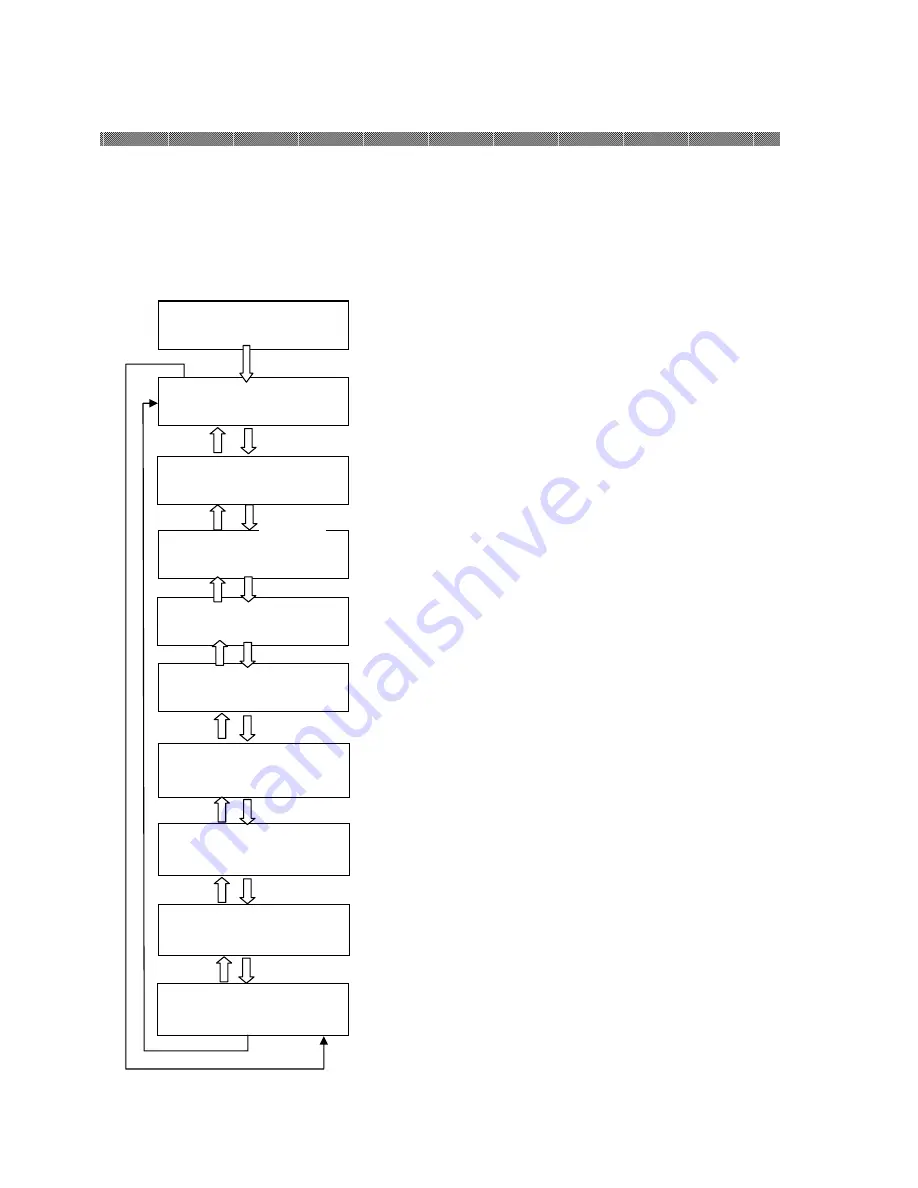
User Set Up Mode 


To set the User Set Up Mode, press the Menu button in standby mode. 
When the MENU button is pressed again, the display changes as follows. 
To change to the standby mode from each menu, press the CLEAR button.   


"XXX" indicates the number of copies that can be printed and "YYY" 
indicates the number of copies that can be printed by one ink ribbon. 
Displays "0/0" when the front cover is opened or a ribbon is not set.


Test print can be performed. 
To execute test print, press the ENTER button. 


Displays the total number of copies printed since the factory shipment.


Displays the version number of the MAN firmware.


Displays the version number of the DSP firmware.


Displays the version number of the print parameter table.


The remaining amount of left side of ribbon is displayed. 

The remaining amount of right side of ribbon is displayed. 


Printed                  □□□□□□ 


Remain                    XXX/YYY 

MENU 


Test Print Mode 

MENU 


8×□□                □□□-□□□ 

MENU 


Donor(L)                    □□□[%] 


MAIN Firm.                =□□□□ 

MENU 


DSP Firm.                  =□□□□ 


TABLE                        =□□□□ 


Donor(L)                    □□□[%] 


TABLE                        =□□□□ 

PAPER SET


PAPER SET


PAPER SET


PAPER SET


PAPER SET


PAPER SET


PAPER SET


PAPER SET


PAPER SET


Содержание DP-1045

Страница 1: ...First edition Aug 8 2011 Latest edition Revision Digital Photo Printer DP 1045 Operation Manual http www sinfo t jp...

Страница 2: ...in any form or by any means including translation without the written permission of SINFONIA TECHNOLOGY Co Ltd 2 The specifications in this operation manual are subject to change without prior notice...

Страница 3: ...t RSS standard s Operation is subject to the following two conditions 1 this device may not cause interference and 2 this device must accept any interference including interference that may cause unde...

Страница 4: ...n 2 7 Transporting the Printer 2 9 Chapter 3 Operation Panel Chapter 3 Operation Panel Chapter 3 Operation Panel Chapter 3 Operation Panel 3 1 Operation Panel 3 1 LCD Display 3 2 User Set Up Mode 3 3...

Страница 5: ...manual all the concern for the safety have to be taken care of at the customer side Operations and the notification for the maintenance described in this manual and other documents are for the proper...

Страница 6: ...Do not place the printer on rickety place and or inclined place Printer may fall down or tumble and it can cause injury Caution Do not place the printer under humid or dusty place It can cause a fire...

Страница 7: ...printer on the slippery floor Warning In case the printer was damaged firstly turn off the power of the printer and remove the power cord then contact the dealers or service center To use the printer...

Страница 8: ...printer Warning Do not attempt to service the printer beyond the instruction specified in this document In case impossible to recover from the problem please contact to the dealers or service center W...

Страница 9: ...re printing to avoid the fingerprints Attention Ink Ribbon Handling Use the ink ribbon specified by Shinko Electric Store the ink ribbon in cool place to avoid the direct sunlight Temperature less tha...

Страница 10: ...Chapter 1 Important Safety Instruction 1 6 MEMO...

Страница 11: ...and remove Outer Box Top Remove Accessory Box and Cushion Top 2 Remove Outer Box Middle And remove slope cardboard and cushion Lower Front Attention Keep the packaging materials The box and protectio...

Страница 12: ...the accessories from the box Check that the following items as illustrated below are present Dust box Tray Paper flange Black Paper flange blue Operation Manua Power cable Caution Make sure to instal...

Страница 13: ...de Upper Cover L Open this cover when inspecting and cleaning the thermal head and cleaning roller and when removing a jamming paper portion Power Switch This switch turns on off the power of the prin...

Страница 14: ...ty to fall down caught by the cord Warning Avoid piled up connection It can cause the fire and electric shock Warning In case of not using the printer for a long time remove the power cord for safety...

Страница 15: ...nstalling Dust Box and Tray 1 Insert the exit tray Slide it downward into the four slots on the printer 2 Insert the dust box Align it with the rail on the side of the printer If the tray is not inser...

Страница 16: ...10 In case paper is replaced go to next step 8 Remove used paper for replacement 9 Remove Paper Flanges from used paper roll 10 Install Paper Flange Blue and Paper Flange Black to new paper roll 11 Th...

Страница 17: ...k and pull out knob of Ribbon Cassette Be careful and operate this step with both hands not to drop the cassette after pullout Lever L2and R2 4 Put the cassette on flat table with handle side to the s...

Страница 18: ...riginal position and confirm the Eject Lever is locked 9 Return the position of Upper unit open Lever to the locked position 10 Close the front cover In case Paper and Ribbon are set and the front cov...

Страница 19: ...ortation method causes a printer fault follow the correct method 1 Remove the ink ribbon and paper from the printer before transporting the printer If the ink ribbon or paper cannot be removed due to...

Страница 20: ...Up 2 10 Repacking Procedure 1 Fix each operation lever of printer and Open and Close Parts of Printer Unit by tapes like below pictures not to open by vibration or shock during transportation Use temp...

Страница 21: ...of slope material Slide the printer on rails slowly and hold up the printer on cushion Bottom Middle 5 Push the printer until Cushion Bottom Rear firmly Caution The weight of this printer is around 7...

Страница 22: ...e 7 Fold back the front side of outer box Bottom and cover a Outer Box Middle and Outer Cover Top in order 8 Allocate Corner Guards to Outer Box Top like left side of picture and band Outer Boxes Bott...

Страница 23: ...Chapter 2 Installing and Set Up 2 13 MEMO...

Страница 24: ...tate the printer is set to a User Set Up mode See page 3 3 Use this button to select an item in the menu Button Not used since the button is for maintenance Button Not used since the button is for mai...

Страница 25: ...alizing Printer is in initialization Ribbon Checking Winding the ink ribbon Paper Loading Paper is being loaded Paper Reloading Paper is being reloaded Printing Printing Cooling Down The thermal head...

Страница 26: ...r is opened or a ribbon is not set Test print can be performed To execute test print press the ENTER button Displays the total number of copies printed since the factory shipment Displays the version...

Страница 27: ...se the lock and pull out knob of Ribbon Cassette Be careful and operate this step with both hands not to drop the cassette after pullout Lever L2and R2 4 When side upper cover of printer left side is...

Страница 28: ...parts of Thermal Head with isopropyl alcohol or ethyl alcohol Right and Left side 7 Using gauze dipped with isopropyl alcohol or ethyl alcohol clean Guide Roller Right and Left side 8 Using gauze dipp...

Страница 29: ...e pinch roller Right and Left side 10 Using gauze dipped with isopropyl alcohol or ethyl alcohol clean the rubber section of the cleaning roller Right and Left side Attention Printing should be perfor...

Страница 30: ...printer outer cabinet Otherwise discoloration or crack may result Warning Continuous use under the abnormal condition such as high temperature smoke and strange smell can cause the fire and electric s...

Страница 31: ...Chapter 4 Routine Maintenance 4 5 MEMO...

Страница 32: ...over Open The paper cover is opened Close the paper cover Front Cover Open The Front Cover is opened Close the Front Cover Ribbon Empty L Run out of Ink Ribbon Left side Replace the Ink Ribbon Left si...

Страница 33: ...mperature sensor in the printer If the printer does not recover from the error after turning power ON and OFF repairs are necessary Consult with the Service Center Upper R L Jam Paper Jam occurred thr...

Страница 34: ...he printer When the paper setting lamp is blinking remove the edge of the paper until the paper setting lamp goes off The front cover does not open Check if the printer is installed in a flat location...

Страница 35: ...it Lever L1and R1 4 Move Cassette Eject Lever in a transverse direction to release the lock and pull out knob of Ribbon Cassette Be careful and operate this step with both hands not to drop the casset...

Страница 36: ...the Steps in the reverse order Caution Make sure that the power is turned off before starting cleaning Thermal Head reaches high temperature just after printing Do not touch directly by hand Make sur...

Страница 37: ...ront cover 2 Push down the Paper Guide Open Lever B to make paper path release position Lever B 3 Rewind paper roll by hand 4 Return the Maintenance Lever B until set position 5 Close the Front Cover...

Страница 38: ...e paper is folded inside of the printer pull it out slowly 11 Close the Paper Load Unit 12 Close the Front Cover Attention If the paper is used without cutting off the folded section or printed sectio...

Страница 39: ...w the instruction below 1 Turn off the power of the printer 2 Turn on the power for 3 or more seconds after turning off the power 3 Paper Jam is displayed on the LCD of the operation panel open the fr...

Страница 40: ...Chapter 6 After sales Service 6 1 Contact your dealers or service center for the details about after sales service...

Страница 41: ...YTE8 J0507E Revision 2011...

Отзывы: