


| 21
Pinouts |
10kW and 25kW Installation Manual
Pinouts
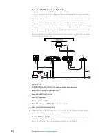
Scanner cable
Pin
Color/Name
AWG
Size
P2
P1
P3
P4
P5
Purpose
1
Blue / Gray (thick)
#16
1
Motor Ground
2
Purple / Brown (thick)
#16
1
Motor Ground
3
White / Orange (thick)
#16
2
Motor Power
4
Red / Green (thick)
#16
2
Motor Power
5
Black / Sky (thick)
#16
1
Scanner
Ground
6
Black
#22
6
Analog
Ground
7
Drain wire (coax line)
#24
2
Video Ground
8
No connection
Not used
9
Yellow / Pink (thick)
#16
Scanner Power
10
Axis line (transparent
insulation)
#24
1
Video
11
Yellow (thin)
#24
3
2
RS-485
Comm+
12
Green (thin)
#24
5
Bearing Zero
13
White (thin)
#24
4
RS-485 Comm-
14
Drain wire
#24
2
Trigger
Ground
15
Shield line
#24
1
Trigger
16
Orange (medium)
#22
3
Bearing Pulse
Shell
Braid shield
Shield
5


