


8
Figure 7. Standard Input Module Default Settings
DIP switch SW1, figure 7, is used to set up the counter to conform to the electrical characteristics
of the sensor or signal being detected. Switch positions 1-3 configure channel B, while switches
4-6 configure channel A. These switches select bias (threshold voltages), low pass filter (enable/
disable) and sensor type (Sink or Source).
Refer to the documentation that accompanied the sensor for related information. The sensor
can most likely be matched to one of the typical switch settings shown in figure 8 and figure 8a.
Note: The input boards are designed so that selecting sourcing or sinking is based on the
type of sensor that is being used. If a PNP (sinking) sensor is being used, set the input
board for sinking also (switches 3 and 6 = OFF).
If channel B is not used, default settings for switch positions 1 through 3 should be selected.
Default settings are provided in Table 2.
The Input module also provides for a user input signal. On the S660, this input serves as a count
enable/disable control. Connecting User to Common will disable counting.
Dipswitch Legend
= ON
= OFF
1 2 3 4 5 6
B
Bias
Off=
H
i
On=Lo
B
Fre
q
Off=
H
i
On=Lo
B
Off=
Sink
On=
Source
A
Fre
q
Off=
H
i
On=Lo
A
Off=
Sink
On=
Source
A
Bias
Off=
H
i
On=Lo
C
H
ANN
E
L
FUNCTION
DIP
Switch
(Shown
for
TTL
Factory
Settings)
Note
:
Refer
to
specifications
for
DIP
switch
function
electrical
characteristics
1
2
3
4
5
6
The S660 can accept inputs from many different sensors. The A and B channels may be
configured independently as shown in Table 2. Figures 8 and 8a have examples of some typical
sensors and the wiring connections that would be used.
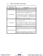
Table 2. Standard Input Module DIP Switch Settings
* = Factory Default setting
1 B Channel Bias
:
OFF =
H
i*
V
LT
=
5
.0 V V
UT
= 7.0V (+/- 10%)
ON = Low
V
LT
= 1.6 V V
UT
= 3.6V (+/- 10%)
2 B Channel Fre
q
uency
:
OFF =
H
i*
(low pass filter disabled)
ON = Lo
(low pass filter enabled)
3 B Channel Sensor
:
OFF = Sinking* (internal pull-up enabled)
ON = Source (internal pull-down enabled)
4 A Channel Bias
:
OFF =
H
i
V
LT
=
5
.0 V V
UT
= 7.0V (+/- 10%)
ON = Low*
V
LT
= 1.6 V V
UT
= 3.6V (+/-10%)
www.
.com
1.800.561.8187


