


SimpliFire • SF-WM36 • 2040-902 Rev. F • 1/14
10
F. Electrical
Connection
WARNING! Risk of Fire, Electrical Shock and Injury.
Electrical wiring must comply with local building codes
and other applicable regulations.
A 15 AMP, 120 Volt, 60 Hz. circuit with a properly
grounded outlet is required. The unit comes with a 6 ft.
(1829 mm) long three wire 16AWG IEC-320 power cord.
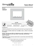
The fi replace power cord has a three pin NEMA-5-15P
plug (Figure 4.9A). An adapter must be used for con-
necting to a two-slot receptacle (Figure 4.9C). The
green grounding wire extending from the adapter must
be connected to a permanent ground such as a properly
grounded outlet box. The adapter should not be used if
a three slot grounded receptacle is available.
Grounding
Pin
Metal Screw
Cover of Grounded
Outlet Box
Grounding
Head
C
B
A
Figure 4.9 Cord Electrical Connection
WARNING! Risk of Fire! Do not plug in or operate this
product with hot air vents touching the ground. Always
hang on wall with supplied bracket before use.
WARNING! Risk of Fire, Electrical Shock, and Injury.
Ensure the power cord is not installed so that it is pinched
or against a sharp edge and ensure that the power cord is
stored or secure to avoid tripping and snagging.
2
1
Secure with
Screw Here
Figure 4.8 Attaching Front to Fireplace
D. Faux Stone Installation
• Arrange the white and clear faux stones along the
inset window ledge at the front of the appliance.
• Place clear stones over LED bulbs and fi ll remaining
gaps with white stones.
Note:
Extra stones are provided and may be
distributed based on consumer preference. Not all
stones need to be used.
E. Glass Front Installation
• Install glass front as shown in Figure 4.8. Orientate
front so that LED lighting connector is towards the fl oor.
• Install glass front so that the tabs on its back side
engage the slots in the top of the appliance.
• Once both tabs engage, press fi rmly against the bottom
face of the glass panel to engage the bottom connectors.
Note:
the tabs on the two center mounting brackets
on the glass will not fully engage the corresponding
slots in the appliance.
• Secure the glass front to the appliance with two
provided M4x8 screw through the two glass front
mounting brackets. See Figure 4.8.
• Connect the electrical cable from the glass front
backlighting to the corresponding cable on the lower
right of the appliance. Note: The backlight cable
plug on the appliance is accessed by removing its
access cover on the lower right of the appliance.


