


6 / 9
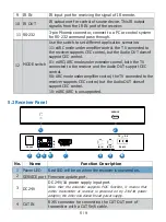
5
Connection
Signal
Indicator LED
(Green)
▪
Illuminated: Transmitter and Receiver are
connected
▪
Flashing: Transmitter and Receiver are not
connected well.
▪
Dark: Transmitter and Receiver are not connected.
6
Data Signal
Indicator LED
(Yellow)
▪
Illuminated: HDMI signal with HDCP.
▪
Flashing: HDMI signal without HDCP.
▪
Dark: No HDMI signal.
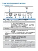
7
HDMI OUT
HDMI signal output port. Connect to TV or amplifier.
8
IR IN
IR input port for receiving the signal of IR remote.
9
IR OUT
IR output port for control of source device. This IR output
signal is from the IR IN port of the transmitter.
10
RS-232
3-pin Phoenix connector, connect to a PC or control system
for RS-232 command pass-through.
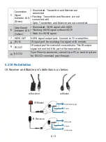
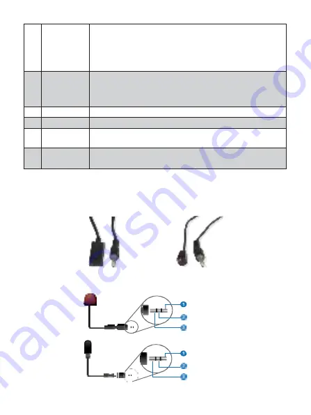
5.3
IR Pin Definition
IR Receiver and Blaster pin’s definition is as below:
IR
Receiver
IR
Blaster
IR Blaster Signal
Power
NC
IR Signal
Power
Grounding
IR Blaster
IR Receiver


